Dell XPS Gen 5 Owner's Manual - Page 103
Installing the Processor Airflow Shroud, Processor, Removing the Processor
 |
View all Dell XPS Gen 5 manuals
Add to My Manuals
Save this manual to your list of manuals |
Page 103 highlights
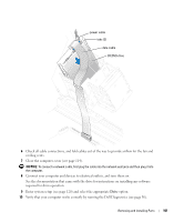
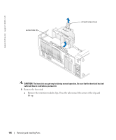
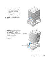
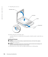
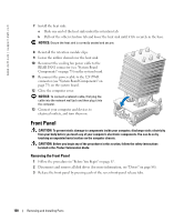
Installing the Processor Airflow Shroud 1 Attach both fan power cables to the connectors on the system board. 2 Align the anchor tabs with the securing slots. 3 Gently press the shroud until the anchor tabs snap securely into place. 4 Close the computer cover. NOTICE: To connect a network cable, first plug the cable into the network wall jack and then plug it into the computer. 5 Connect your computer and devices to electrical outlets, and turn them on. Processor Removing the Processor NOTICE: Do not perform the following steps unless you are familiar with hardware removal and replacement. Performing these steps incorrectly could damage your system board. For technical service, see "Dell Technical Support Policy (U.S. Only)" on page 129. CAUTION: Before you begin any of the procedures in this section, follow the safety instructions located in the Product Information Guide. 1 Follow the procedures in "Before You Begin" on page 67. 2 Disconnect the cooling fan power cable from the REAR FAN1 connector (see "System Board Components" on page 75) on the system board. 3 Disconnect the power cable from the 12V PWR connector (see "System Board Components" on page 75) on the system board. 4 Lift up the airflow shroud. Removing and Installing Parts 103
-
 1
1 -
2
-
3
-
4
-
5
-
6
-
7
-
8
-
9
-
10
-
11
-
12
-
13
-
14
-
15
-
16
-
17
-
18
-
19
-
20
-
21
-
22
-
23
-
24
-
25
-
26
-
27
-
28
-
29
-
30
-
31
-
32
-
33
-
34
-
35
-
36
-
37
-
38
-
39
-
40
-
41
-
42
-
43
-
44
-
45
-
46
-
47
-
48
-
49
-
50
-
51
-
52
-
53
-
54
-
55
-
56
-
57
-
58
-
59
-
60
-
61
-
62
-
63
-
64
-
65
-
66
-
67
-
68
-
69
-
70
-
71
-
72
-
73
-
74
-
75
-
76
-
77
-
78
-
79
-
80
-
81
-
82
-
83
-
84
-
85
-
86
-
87
-
88
-
89
-
90
-
91
-
92
-
93
-
94
-
95
-
96
-
97
-
 98
98 -
 99
99 -
 100
100 -
 101
101 -
 102
102 -
 103
103 -
 104
104 -
 105
105 -
 106
106 -
 107
107 -
 108
108 -
109
-
110
-
111
-
112
-
113
-
114
-
115
-
116
-
117
-
118
-
119
-
120
-
121
-
122
-
123
-
124
-
125
-
126
-
127
-
128
-
129
-
130
-
131
-
132
-
133
-
134
-
135
-
136
-
137
-
138
-
139
-
140
-
141
-
142
-
143
-
144
-
145
-
146
-
147
-
148
-
149
-
150
-
151
-
152
-
153
-
154
 |
 |