Denon 1706 Owners Manual - Page 14
Connecting Other Sources - avr video off
 |
UPC - 081757506526
View all Denon 1706 manuals
Add to My Manuals
Save this manual to your list of manuals |
Page 14 highlights
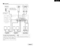
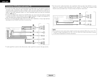
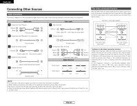
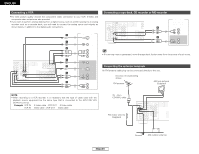
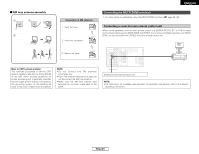
ENGLISH Connecting Other Sources Cable indications The hookup diagrams on the subsequent pages assume the use of the following optional connection cables (not supplied). Audio cable A Analog terminal (Stereo) (White) (Red) L L R R Pin-plug cable B Analog terminal (Monaural, for subwoofer) F Video terminal Video cable (Yellow) Video cable (75 Ω/ohm video pin-plug cable) G S-Video terminal Pin-plug cable C Digital terminal (Coaxial) (Orange) Coaxial cable (75 Ω/ohm pin-plug cable) D Digital terminal (Optical) Optical cable (Optical fiber cable) E Speaker terminal Speaker cable S-Video cable H Component video terminal (Green) (Blue) (Red) Component video cable Signal direction Audio signal IN Video signal IN OUT OUT OUT OUT (Y) (PB/CB) (PR/CR) IN IN Connecting Other Sources The video conversion function With the AVR-1706, the Video signal and the S-Video signal which were inputted are mutually converted. And also the Video signal and the S-Video signal which were inputted are converted into a higher quality. The flow of the video signals. (Component video terminals) (S-Video terminal) (Video terminal) This unit's input terminals (Component video terminals) (S-Video terminal) (Video terminal) This unit's output terminals Cautions on the video conversion function: When the component video terminals are used to connect the AVR-1706 with a TV (or monitor, projector, etc.) and the video (yellow) or S-Video terminals are used to connect the AVR1706 with a VTR, depending on the combination of the TV and VTR the picture may flicker in the horizontal direction, be distorted, be out of sync not display at all when playing video tapes. If this happens, connect a commercially available video stabilizer, etc., with a TBC (time base corrector) function between the AVR-1706 and the VTR, or if your VTR has a TBC function, turn it on. NOTE: • Do not plug in the power supply cord until all connections have been completed. • When making connections, also refer to the operating instructions of the other components. • Be sure to connect the left and right channels properly (left with left, right with right). • Note that binding pin-plug cables together with power supply cords or placing them near a power transformer will result in hum or other noise. 11 ENGLISH
-
 1
1 -
2
-
3
-
4
-
5
-
6
-
7
-
8
-
 9
9 -
 10
10 -
 11
11 -
 12
12 -
 13
13 -
 14
14 -
 15
15 -
 16
16 -
 17
17 -
 18
18 -
 19
19 -
20
-
21
-
22
-
23
-
24
-
25
-
26
-
27
-
28
-
29
-
30
-
31
-
32
-
33
-
34
-
35
-
36
-
37
-
38
-
39
-
40
-
41
-
42
-
43
-
44
-
45
-
46
-
47
-
48
-
49
-
50
-
51
-
52
-
53
-
54
-
55
-
56
-
57
-
58
-
59
-
60
-
61
 |
 |
