Denon 1706 Owners Manual - Page 6

Operating range of the remote control unit, Part names and functions, Inserting the batteries - setup

Page 6 highlights

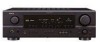
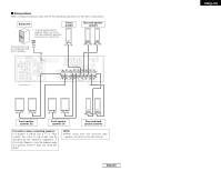
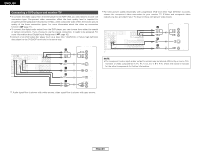
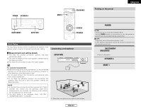
ENGLISH Getting Started Inserting the batteries q Remove the remote control unit's rear cover. w Set two R6P/AA batteries in the battery compartment in the indicated direction. e Put the rear cover back on. Notes on batteries: • Replace the batteries with new ones if the set does not operate even when the remote control unit is operated nearby the unit. (The included batteries are only for verifying operation.) • When inserting the batteries, be sure to do so in the proper direction, following the "" marks in the battery compartment. • To prevent damage or leakage of battery fluid: • Do not use a new battery together with an old one. • Do not use two different types of batteries. • Do not short-circuit, disassemble, heat or dispose of batteries in flames. • If the battery fluid should leak, carefully wipe the fluid off the inside of the battery compartment and insert new batteries. • When replacing the batteries, have the new batteries ready and insert them as quickly as possible. Part names and functions Getting Started Front panel For details on the functions of these parts, refer to the pages given in parentheses ( ). @7 @2 @0 #3 #2 #1 #0 @9 @8 @6 @5 @4 @3 @1 !9 t u o !1 q w e r y i !0 !4 !2 !3 !5 !6 !7 !8 Operating range of the remote control unit • Point the remote control unit at the remote sensor on the main unit as shown in the diagram. • The remote control unit can be used from a straight distance of approximately 23 feet from the main unit, but this distance will be shorter if there are obstacles in the way or if the remote control unit is not pointed directly at the remote sensor. • The remote control unit can be operated at a horizontal angle of up to 30 degrees with respect to the remote sensor. Approx. 23 feet 30° 30° NOTE: • It may be difficult to operate the remote control unit if the remote sensor is exposed to direct sunlight or strong artificial light. • Do not press buttons on the main unit and remote control unit simultaneously. Doing so may result in malfunction. • Neon signs or other devices emitting pulsetype noise nearby may result in malfunction, so keep the set as far away from such devices as possible. q Power ON/STANDBY switch 8) w Power indicator 8) e Power switch 8, 37) r Headphones jack (PHONES 17) t ANALOG button 18) y SPEAKER A/B buttons 17, 37) u ZONE2 button 35) i Preset station select buttons 29, 30) o STANDARD/NIGHT button 19~24) !0 5CH/7CH STEREO button 25) !1 DIRECT/STEREO button 18) !2 V. AUX INPUT terminals 12) !3 SETUP MIC jack 8) !4 SURROUND MODE button 16) !5 SURROUND PARAMETER button 19) !6 SELECT knob 16, 19, 28) !7 TONE DEFEAT button 28) !8 TONE CONTROL button 28) !9 MASTER VOLUME control knob 16) @0 TUNING • (up)/ª (down) buttons ·····(29) @1 STATUS button 17, 23) @2 DIMMER button 17) @3 VIDEO SELECT button 17) @4 OUTPUT indicator 22) @5 Master volume indicator 16) @6 Display @7 INPUT mode indicator 18) @8 SIGNAL indicator 18) @9 BAND button 29) #0 EXT. IN button 16) #1 Remote control sensor 3) #2 INPUT MODE button 17) #3 INPUT SELECTOR knob 16) 3 ENGLISH

  • 1
  • 2
  • 3
  • 4
  • 5
  • 6
  • 7
  • 8
  • 9
  • 10
  • 11
  • 12
  • 13
  • 14
  • 15
  • 16
  • 17
  • 18
  • 19
  • 20
  • 21
  • 22
  • 23
  • 24
  • 25
  • 26
  • 27
  • 28
  • 29
  • 30
  • 31
  • 32
  • 33
  • 34
  • 35
  • 36
  • 37
  • 38
  • 39
  • 40
  • 41
  • 42
  • 43
  • 44
  • 45
  • 46
  • 47
  • 48
  • 49
  • 50
  • 51
  • 52
  • 53
  • 54
  • 55
  • 56
  • 57
  • 58
  • 59
  • 60
  • 61

3
ENGLISH
ENGLISH
Getting Started
Getting Started
Operating range of the remote control unit
30°
30°
Approx. 23 feet
• Point the remote control unit at the remote sensor on the main unit as shown in the diagram.
• The remote control unit can be used from a straight distance of approximately 23 feet from the
main unit, but this distance will be shorter if there are obstacles in the way or if the remote control
unit is not pointed directly at the remote sensor.
• The remote control unit can be operated at a horizontal angle of up to 30 degrees with respect
to the remote sensor.
NOTE:
• It may be difficult to operate the remote control
unit if the remote sensor is exposed to direct
sunlight or strong artificial light.
• Do not press buttons on the main unit and
remote control unit simultaneously. Doing so
may result in malfunction.
• Neon signs or other devices emitting pulse-
type noise nearby may result in malfunction,
so keep the set as far away from such devices
as possible.
Part names and functions
Front panel
For details on the functions of these parts, refer to the pages given in parentheses (
).
#
3
#
1
@
9
#
2
#
0
@
6
@
8
@
5
@
4
@
1
!
9
@
3
@
2
@
0
@
7
r
y
i
!
0
!
2
!
5
!
3
!
6
!
7
!
8
q
w
t
e
u
o
!
1
!
4
q
Power ON/STANDBY switch
················(8)
w
Power indicator
······································(8)
e
Power switch
···································(8, 37)
r
Headphones jack (PHONES)
···············(17)
t
ANALOG button
···································(18)
y
SPEAKER A/B buttons
··················(17, 37)
u
ZONE2 button
······································(35)
i
Preset station select buttons
·······(29, 30)
o
STANDARD/NIGHT button
···········(19~24)
!
0
5CH/7CH STEREO button
···················(25)
!
1
DIRECT/STEREO button
······················(18)
!
2
V. AUX INPUT terminals
·····················(12)
!
3
SETUP MIC jack
·····································(8)
!
4
SURROUND MODE button
·················(16)
!
5
SURROUND PARAMETER
button
···················································(19)
!
6
SELECT knob
····························(16, 19, 28)
!
7
TONE DEFEAT button
··························(28)
!
8
TONE CONTROL button
······················(28)
!
9
MASTER VOLUME control knob
········(16)
@
0
TUNING
(up)/
ª
(down) buttons
·····(29)
@
1
STATUS button
······························(17, 23)
@
2
DIMMER button
···································(17)
@
3
VIDEO SELECT button
·························(17)
@
4
OUTPUT indicator
································(22)
@
5
Master volume indicator
·····················(16)
@
6
Display
@
7
INPUT mode indicator
·························(18)
@
8
SIGNAL indicator
·································(18)
@
9
BAND button
········································(29)
#
0
EXT. IN button
······································(16)
#
1
Remote control sensor
··························(3)
#
2
INPUT MODE button
···························(17)
#
3
INPUT SELECTOR knob
·······················(16)
Inserting the batteries
q
Remove the remote control unit’s rear
cover.
w
Set two R6P/AA batteries in the battery
compartment in the indicated direction.
e
Put the rear cover back on.
Notes on batteries:
• Replace the batteries with new ones if the set
does not operate even when the remote
control unit is operated nearby the unit. (The
included batteries are only for verifying
operation.)
• When inserting the batteries, be sure to do so
in the proper direction, following the “
<
” and
>
” marks in the battery compartment.
• To prevent damage or leakage of battery fluid:
• Do not use a new battery together with an
old one.
• Do not use two different types of batteries.
• Do not short-circuit, disassemble, heat or
dispose of batteries in flames.
• If the battery fluid should leak, carefully wipe
the fluid off the inside of the battery
compartment and insert new batteries.
• When replacing the batteries, have the new
batteries ready and insert them as quickly as
possible.