Denon AVR-4800 Owners Manual - Page 6
Connections - remote control
 |
View all Denon AVR-4800 manuals
Add to My Manuals
Save this manual to your list of manuals |
Page 6 highlights
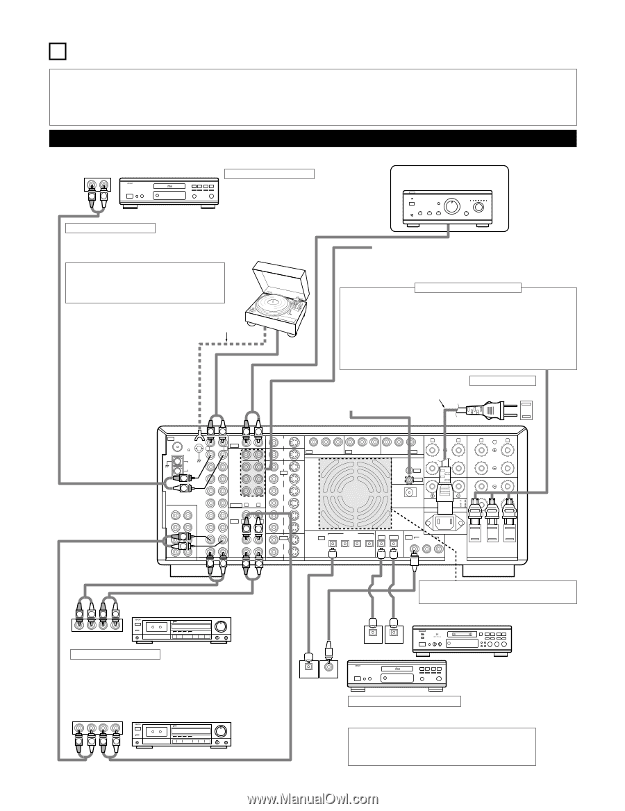
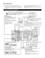
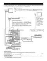
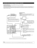
5 CONNECTIONS • Do not plug in the AC cord until all connections have been completed. • Be sure to connect the left and right channels properly (left with left, right with right). • Insert the plugs securely. Incomplete connections will result in the generation of noise. • Use the AC OUTLETS for audio equipment only. Do not use them for hair dryers, etc. • Note that binding pin plug cords together with AC cords or placing them near a power transformer will result in generating hum or other noise. • Noise or humming may be generated if a connected audio equipment is used independently without turning the power of this unit on. If this happens, turn on the power of the this unit. Connecting the audio components • When making connections, also refer to the operating instructions of the other components. OUTPUT RL CD player RL DIGITAL AUDIO Connecting a CD player Connect the CD player's analog output jacks (ANALOG OUTPUT) to this unit's CD jacks using pin plug cords. Pre-main (integrated) amplifier for multi-source playback B Connecting a turntable Connect the turntable's output cord to the AVR4800's PHONO jacks, the L (left) plug to the L jack, the R (right) plug to the right jack. NOTE: This unit cannot be used with MC cartridges directly. Use a separate head amplifier or step-up transformer. Turntable (MM cartridge) If humming or other noise is generated when the ground wire is connected, disconnect the ground wire. Ground wire Connecting the pre-out jacks Use these jacks if you wish to connect external power amplifier(s) to increase the power of the front, center and surround sound channels, or for connection to powered loudspeakers. For instructions on using the effect output, refer to page 44. Connecting the AC OUTLETS AC OUTLETS • SWITCHED (total capacity - 120 W (1 A.)) The power to these outlets is turned on and off in conjunction with the POWER switch on the main unit, and when the power is switched between on and standby from the remote control unit. No power is supplied from these outlets when this unit's power is at standby. Never connect equipment whose total capacity is above 120 W (1 A.) NOTE: Only use the AC OUTLETS for audio equipment. Never use them for hair dryers, TVs or other electrical appliances. Extension jacks for future use AC cord (Supplied) AC outlets (wall) AC 120V, 60Hz IN AM R FM PHONO COAX. 75 R SIGNAL CD GND LOOP ANT. DVD R VDP ANTENNA TERLMINALS TV/ DBS 6CH EXT. IN V.AUX FR FL VCR-1 SW C VCR-2 R SR SL MD/ TAPE-1 L ER EL TAPE-2 8CH EXT. IN R L RL MULTI SOURCE OUT L FRONT CENTER SUB WOOFER SURROUND MONITOR OUT-1 MONITOR OUT-2 DVD IN VDP Y IN CB CR Y CB CR DVD IN TV/DBS COMPONENT VIDEO Y CB CR MONITOR OUT ROOM TO ROOM REMOTE CONTROL IN OUT FRONT R / EFECT, SB L SB-R SB / SB-L SURROUND R A L EFECT / SB SB/ SB-R SB-L PRE OUT R L TV / DBS V.AUX VCR-1 OUT R VCR-2 R MD / TAPE-1 TAPE-2 AUDIO L R VCR-1 L L VCR-2 OUT VCR-1 VCR-2 VIDEO L S-VIDEO POWER AMP REMOTE CONTROL CENTER FRONT / EFECT, SB / CENTER: 6 16 SURROUND / A OR B : 6 16 A+B : 8 16 SPEAKER SYSTEMS AC IN R B L SURROUND IN 1 OPTICAL 2 3 OPTICAL-5 4 IN OUT IN COAXIAL 1 2 3 DIGITAL SWITCHED TOTAL 120W(1A.) MAX. AC 120V 60Hz AC OUTLETS R LR L Tape deck 2 R LRL OUTPUT INPUT Connecting a tape deck Connections for recording: Connect the tape deck's recording input jacks (LINE IN or REC) to this unit's tape recording (OUT) jacks using pin plug cords. Connections for playback: Connect the tape deck's playback output jacks (LINE OUT or PB) to this unit's tape playback (IN) jacks using pin plug cords. OUTPUT INPUT R LRL Tape deck 1 or MD recorder R LR L OUTPUT INPUT OPTICAL Route the connection cords, etc., in such a way that they do not obstruct the ventilation holes. MD recorder, DAT deck or other component equipped with digital input/output jacks B OPTICAL COAXIAL OUTPUT DIGITAL AUDIO CD player or other component equipped with digital output jacks Connecting the DIGITAL jacks Use these for connections to audio equipment with digital output. Refer to page 28 for instructions on setting this terminal. NOTES: • Use 75 Ω/ohms cable pin cords for coaxial connections. • Use optical cables for optical connections, removing the cap before connecting. 6
-
 1
1 -
 2
2 -
 3
3 -
 4
4 -
 5
5 -
 6
6 -
 7
7 -
 8
8 -
 9
9 -
 10
10 -
 11
11 -
 12
12 -
13
-
14
-
15
-
16
-
17
-
18
-
19
-
20
-
21
-
22
-
23
-
24
-
25
-
26
-
27
-
28
-
29
-
30
-
31
-
32
-
33
-
34
-
35
-
36
-
37
-
38
-
39
-
40
-
41
-
42
-
43
-
44
-
45
-
46
-
47
-
48
-
49
-
50
-
51
-
52
-
53
-
54
-
55
-
56
-
57
-
58
-
59
-
60
-
61
-
62
-
63
-
64
-
65
-
66
-
67
-
68
-
69
 |
 |