Denon DN-C640 Operating Instructions - Page 44
Rs-232c Control
 |
UPC - 081757507608
View all Denon DN-C640 manuals
Add to My Manuals
Save this manual to your list of manuals |
Page 44 highlights
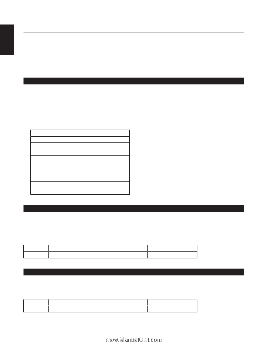
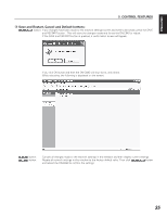
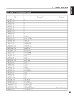
ENGLISH 5. CONTROL FEATURES RS-232C CONTROL Connect a male (D-Sub 9 Pin) to female (D-Sub 9 Pin) straight cable for RS-232C external control by host equipment. • The RS-232C host can control functions of the DN-C640 externally • The DN-C640 automatically transmits status data when status is changed. • The DN-C640 will respond to status requests by transmitting the associated status data RS-232C specifications: (1) Interface Condition • Applicable connector : 9-pin D-sub (male) • Baud rate : 9600 bps • Data Bit : 8bit • Parity : None • Stop bit : 1bit • Flow control : None • Pin layout RS-232C Pin No 1 6 2 7 3 8 4 9 5 Signal Name Ground NC TxD NC RxD NC NC NC S. Ground (2) Control command codes The control command packets have a data length of 7 bytes or more. ASCII codes from 0x00 to 0x7F are used to receive serial data. At the transmission end, take steps to convert the ASCII codes into HEX data to set the data in the data packets. CR (0x0D) is added as the data packet delimiter. Example: Control command code for number 5 (ASCII code @02005CR) When transmitting commands consecutively, put more than 100ms blank between commands. @ 0 × 40 0 0 × 30 2 0 × 32 0 0 × 30 0 0 × 30 5 0 × 35 CR 0 × 0d (3) Status Request and Status Information codes The status data packets have a data length of 7 bytes or more. ASCII codes from 0 × 00 to 0 × 7f are used to transmit serial data. For this reason, the ASCII codes are converted into HEX data before the data is set in the data packets and transmitted. CR (0 × 0d) is added as the data packet delimiter. Example: Status Information code "Disc In" (ASCII code @0 CDCI CR) @ 0 × 40 0 0 × 30 C 0 × 43 D 0 × 44 C 0 × 43 I 0 × 49 CR 0 × 0d 36
-
 1
1 -
2
-
3
-
4
-
5
-
6
-
7
-
8
-
9
-
10
-
11
-
12
-
13
-
14
-
15
-
16
-
17
-
18
-
19
-
20
-
21
-
22
-
23
-
24
-
25
-
26
-
27
-
28
-
29
-
30
-
31
-
32
-
33
-
34
-
35
-
36
-
37
-
38
-
 39
39 -
 40
40 -
 41
41 -
 42
42 -
 43
43 -
 44
44 -
 45
45 -
 46
46 -
 47
47 -
 48
48 -
 49
49 -
50
-
51
-
52
-
53
-
54
 |
 |