Denon DN-T625 Operating Instructions - Page 8
CONNECTIONS, Tape counter - remote control
 |
UPC - 081757505208
View all Denon DN-T625 manuals
Add to My Manuals
Save this manual to your list of manuals |
Page 8 highlights
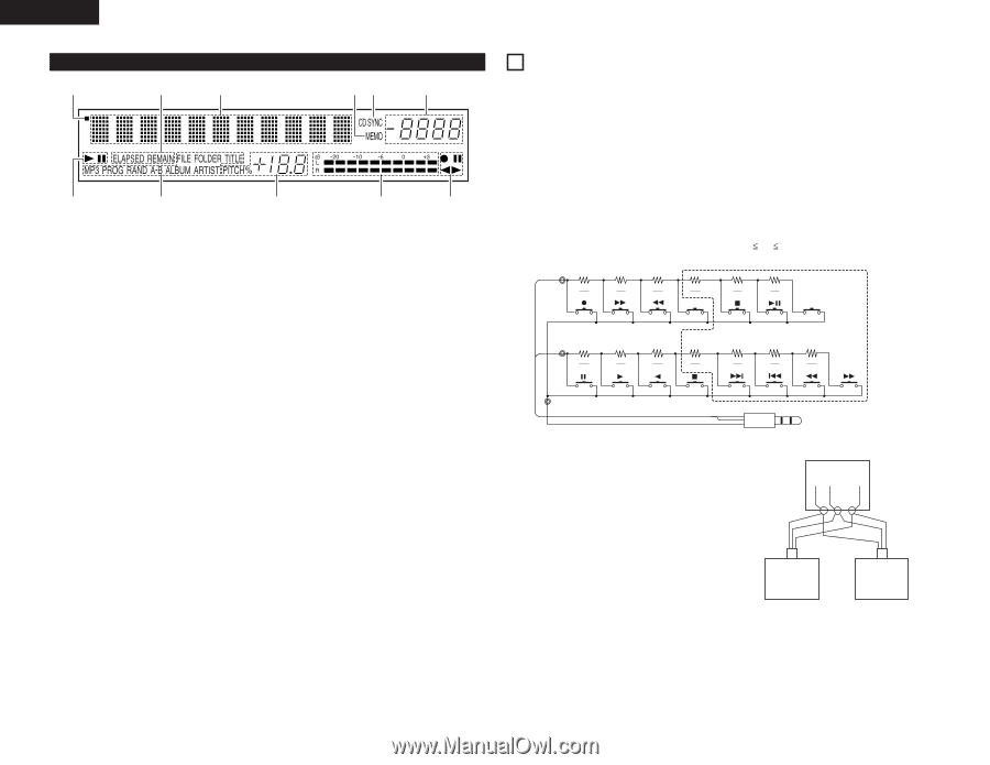
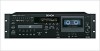
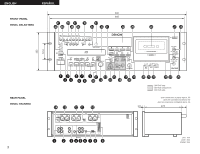
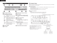
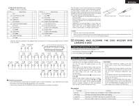
ENGLISH (3) Display !1 !0 o iu y q w e r t q CD transport indicator w Mode display portion (CD) • Indicator for MP3 is DN-T645 only. FILE : This lights when the file name of MP3 is displayed. FOLDER : This lights in the folder selection mode. TITLE : This lights when the title in the MP3 ID3-Tag or CD Text is displayed. MP3 : This lights when a disc containing MP3 format file is loaded. PROG : This lights in the program mode. RAND : This lights in the random mode. A-B : This lights in the A-B repeat playback mode. ALBUM : This lights when the album name in the MP3 ID3-Tag is displayed. ARTIST : This lights when the artist name in the MP3 ID3-Tag is displayed. e CD pitch display r Level meter t Cassette deck transport indicator y Tape counter u CD synchronized recording indicator • This lights in the CD synchronized recording mode. i Memory stop indicator o Multiple display • This displays Track No. of CD, playing time of CD, various operational information, text message, etc. !0 Time mode indicator ELAPSED : This lights when the elapsed time is displayed. REMAIN : This lights when the remaining time is displayed. !1 Infrared remote control indicator 3 CONNECTIONS Leave your entire system (including the DN-T645/625) turned off until all connections between the DN-T645/625 and other components have been completed. 2 Connection precautions • Before proceeding with connections or disconnections of cables and power cords, be sure to turn all system components off. • Ensure that all cables are connected properly to the L (left) and R (right) jacks. • Insert plugs fully into the terminals. • Connect the CD output jacks to the amplifier CD or AUX input jacks. 2 Remote control connections (1) RC IN • For wired remote control, use the circuit shown on the diagram below. • Design the circuit so that the wire resistance is 0.5 Ω/ohms or less. ✽1 N 6 ("N" is the number of DN-T645/625 units connected.) C1 Lch 150 180 270 390 N N N N 680 1.3k N N COUNTER CUE DECK UNIT C2 Rch 150 180 270 390 N N N N CD UNIT 680 1.3k 3.9k N N N GND C3 Rch Lch GND G R L ø3.5mm STEREO MINI PLUG • Up to six units can be controlled simultaneously with one remote control unit. • Wire the signal and ground lines as shown on the diagram below and connect at the remote control inputs (C1, C2 and C3). • Design the circuit so that the resistance of the individual wires is 0.5 Ω/ohms or less. Connecting two DN-T645/625 units (N = 2) Remote Unit C1 C2 C3 DN-T645/625 1 DN-T645/625 2 8
-
 1
1 -
2
-
 3
3 -
 4
4 -
 5
5 -
 6
6 -
 7
7 -
 8
8 -
 9
9 -
 10
10 -
 11
11 -
 12
12 -
 13
13 -
14
-
15
-
16
-
17
-
18
-
19
-
20
-
21
-
22
-
23
-
24
-
25
-
26
-
27
-
28
-
29
-
30
-
31
-
32
-
33
-
34
-
35
-
36
-
37
-
38
 |
 |