Dewalt D28065N Instruction Manual - Page 10
Components Fig. 1, Assembly And Adjustments - d28065 grinder
 |
View all Dewalt D28065N manuals
Add to My Manuals
Save this manual to your list of manuals |
Page 10 highlights
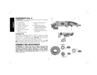
English COMPONENTS (Fig. 1) WARNING: Never modify the power tool or any part of it. Damage or personal injury could result. A. Trigger Switch B. Lock On Button (D28065, D28115 only) C. Spindle Lock Button D. Type 27 Guard E. Dust Ejection System™ (DES) F. Yellow Rubber Ring G1. Quick-Change Backing Flange G2. Stamped Steel QuickChange Backing Flange (D28065, D28065N only) H. Threaded Clamp Nut I. Anti-Vibration Side Handle (not shown) INTENDED USE The D28065, D26065N, D28115, D28115N heavy-duty angle grinders have been designed for professional grinding at various work sites (i.e., construction sites). DO NOT use under wet conditions or in presence of flammable liquids or gases. These heavy-duty angle grinders are professional power tools. DO NOT let children come into contact with the tool. Supervision is required when inexperienced operators use this tool. ASSEMBLY AND ADJUSTMENTS WARNING: To reduce the risk of injury, turn unit off and disconnect it from power source before installing and removing accessories, before adjusting or when making repairs. Before reconnecting the tool, depress and release the trigger switch to ensure that the tool is off. An accidental startup can cause injury. FIG. 1 C F 8 B D A E E G1 H G2
-
 1
1 -
2
-
3
-
4
-
 5
5 -
 6
6 -
 7
7 -
 8
8 -
 9
9 -
 10
10 -
 11
11 -
 12
12 -
 13
13 -
 14
14 -
 15
15 -
16
-
17
-
18
-
19
-
20
-
21
-
22
-
23
-
24
-
25
-
26
-
27
-
28
-
29
-
30
-
31
-
32
-
33
-
34
-
35
-
36
-
37
-
38
-
39
-
40
-
41
-
42
-
43
-
44
-
45
-
46
-
47
-
48
-
49
-
50
-
51
-
52
-
53
-
54
-
55
-
56
-
57
-
58
-
59
-
60
-
61
-
62
-
63
-
64
-
65
-
66
-
67
-
68
-
69
-
70
-
71
-
72
 |
 |
