Dewalt D28065N Instruction Manual - Page 15
Mounting and Using Depressed Center, Grinding Wheels and Sanding Flap Discs - d28065
 |
View all Dewalt D28065N manuals
Add to My Manuals
Save this manual to your list of manuals |
Page 15 highlights
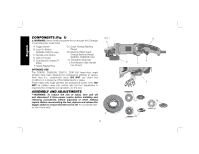
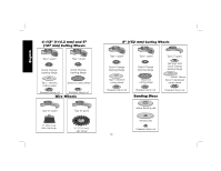
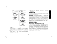
English CAUTION: Before connecting the tool to a power source depress and release the trigger switch (A) once without depressing the lock-on button (B) to ensure that the switch is off. Depress and release the trigger switch as described above after any interruption in power supply to the tool, such as the activation of a ground fault interrupter, throwing of a circuit breaker, accidental unplugging, or power failure. To turn the tool on, depress the trigger switch (A). The tool will run while the switch is depressed. Turn the tool off by releasing the trigger switch. LOCK-ON BUTTON (D28065, D28115) (FIG. 5) The lock-on button (B) offers increased comfort FIG. 5 in extended use applications. To lock the tool on, depress the trigger switch (A), then push the lock-on button (B). The tool will continue to run after the trigger switch is released. To unlock the tool, depress and release the trigger switch. This will cause the tool to stop. CAUTION: Allow the tool to reach full B A speed before touching tool to the work surface. Lift the tool from the work surface before turning the tool off. SPINDLE LOCK (FIG. 6) The spindle lock (C) is provided to prevent the spindle from rotating when installing or removing wheels. Operate the spindle lock only when the tool is turned off, unplugged from the power supply, and has come to a complete stop. Do not engage the spindle lock while the tool is operating because damage to the tool will result. To engage the lock, depress the spindle lock button and rotate the spindle until you are unable to rotate the spindle further. FIG. 6 C Mounting and Using Depressed Center Grinding Wheels and Sanding Flap Discs MOUNTING AND REMOVING HUBBED WHEELS Hubbed wheels install directly on the 5/8"-11 threaded spindle. Thread of accessory must match thread of spindle. 1. Backing flange is retained to the grinder by an O-ring on the spindle. Remove backing flange by pulling and twisting flange away form the machine. 2. Thread the wheel on the spindle by hand. 3. Depress the spindle lock button and use a wrench to tighten the hub of the wheel. 4. Reverse the above procedure to remove the wheel. CAUTION: Failure to properly seat the wheel before turning the tool on may result in damage to the tool or the wheel. MOUNTING NON-HUBBED WHEELS (FIG. 7, 8) Depressed center Type 27 grinding wheels must be used with included flanges. NOTE: The stamped steel quick-change FIG. 7 backing flange (G2) is for use with D28065 G1, G2 and D28065N for Type 27 grinding wheels only. Refer to pages 9-11 for more information. 1. Install the stamped steel quick-change backing flange (G2) (D28065, D28065N N only) for Type 27 6" (152 mm) wheels or the quick-change backing flange (G1) for all other non-hubbed wheels on spindle (N) with the raised section (pilot) against the wheel. Be sure the backing flange recess is seated onto the flats of the H spindle by pushing and twisting the flange before placing wheel. 13
-
 1
1 -
2
-
3
-
4
-
5
-
6
-
7
-
8
-
9
-
 10
10 -
 11
11 -
 12
12 -
 13
13 -
 14
14 -
 15
15 -
 16
16 -
 17
17 -
 18
18 -
 19
19 -
 20
20 -
21
-
22
-
23
-
24
-
25
-
26
-
27
-
28
-
29
-
30
-
31
-
32
-
33
-
34
-
35
-
36
-
37
-
38
-
39
-
40
-
41
-
42
-
43
-
44
-
45
-
46
-
47
-
48
-
49
-
50
-
51
-
52
-
53
-
54
-
55
-
56
-
57
-
58
-
59
-
60
-
61
-
62
-
63
-
64
-
65
-
66
-
67
-
68
-
69
-
70
-
71
-
72
 |
 |
