Dewalt D28065N Instruction Manual - Page 14
OPERATION, Guards and Flanges, Trigger Switch Fig. 1, 5, 6
 |
View all Dewalt D28065N manuals
Add to My Manuals
Save this manual to your list of manuals |
Page 14 highlights
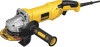
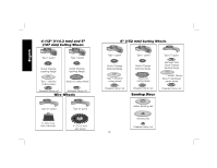
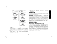
English 1. Open the guard latch (J). Align the lugs (K) on FIG. 3 the guard with the slots (L) on the gear K case. 2. Push the guard down until the guard lugs engage and rotate freely in the groove on the gear case hub. 3. With the guard latch open, rotate the guard L (D) into the desired working position. The J guard body should be positioned between the spindle and the operator to provide maximum operator protection. 4. Close the guard latch to secure the guard on the gear case. You should not be able to rotate the guard by hand when the latch D is closed. Do not operate the grinder with a loose guard or the clamp lever in open position. 5. To remove the guard, open the guard latch, rotate the guard so that the arrows are aligned and pull up on the guard. NOTE: The guard is pre-adjusted to the FIG. 4 diameter of the gear case hub at the factory. If, after a period of time, the guard becomes M loose, tighten the adjusting screw (M) with clamp lever in the closed position. CAUTION: Do not tighten the adjusting screw with the clamp lever in open position. Undetectable damage to the guard or the mounting hub may result. CAUTION: If guard cannot be tightened by adjusting clamp, do not use tool and take the tool and guard to a service center to repair or replace the guard. OPERATION WARNING: To reduce the risk of injury, turn unit off and disconnect it from power source before installing and removing accessories, before adjusting or when making repairs. Before reconnecting the tool, depress and release the trigger switch to ensure that the tool is off. An accidental start-up can cause injury. Guards and Flanges It is important to choose the correct guards and flanges to use with the grinder accessories. See pages 9-11 for the correct accessories. NOTE: Edge grinding and cutting can be performed with Type 27 wheels designed and specified for this purpose. WARNING: Accessories must be rated for at least the speed recommended on the tool warning label. Wheels and other accessories running over rated accessory speed may burst and cause injury. Every unthreaded accessory must have a 7/8" (22.2 mm) arbor hole. If it does not, it may have been designed for a circular saw and should not be used. Use only the accessories shown on pages 9-11. Accessory ratings must be above listed minimum wheel speed as shown on tool nameplate. Trigger Switch (Fig. 1, 5, 6) CAUTION: Hold the side handle and body of the tool firmly to maintain control of the tool at start up and during use and until the wheel or accessory stops rotating. Make sure the wheel has come to a complete stop before laying the tool down. NOTE: To reduce unexpected tool movement, do not switch the tool on or off while under load conditions. Allow the grinder to run up to full speed before touching the work surface. Lift the tool from the surface before turning the tool off. Allow the tool to stop rotating before putting it down. 12
-
 1
1 -
2
-
3
-
4
-
5
-
6
-
7
-
8
-
 9
9 -
 10
10 -
 11
11 -
 12
12 -
 13
13 -
 14
14 -
 15
15 -
 16
16 -
 17
17 -
 18
18 -
 19
19 -
20
-
21
-
22
-
23
-
24
-
25
-
26
-
27
-
28
-
29
-
30
-
31
-
32
-
33
-
34
-
35
-
36
-
37
-
38
-
39
-
40
-
41
-
42
-
43
-
44
-
45
-
46
-
47
-
48
-
49
-
50
-
51
-
52
-
53
-
54
-
55
-
56
-
57
-
58
-
59
-
60
-
61
-
62
-
63
-
64
-
65
-
66
-
67
-
68
-
69
-
70
-
71
-
72
 |
 |
