Dewalt D55154 Instruction Manual - Page 10
Save These Instructions, For Future Use, Features Fig. 1 - regulator
 |
View all Dewalt D55154 manuals
Add to My Manuals
Save this manual to your list of manuals |
Page 10 highlights
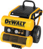
English CAUTION: risk from noise What can happen How to prevent it • Under some conditions and duration of use, noise from this product may contribute to hearing loss. • Always wear certified safety equipment: ANSI S12.6 (S3.19) hearing protection. SAVE THESE INSTRUCTIONS FOR FUTURE USE Features (Fig. 1) On/Off Switch Place this switch (A) in the ON position to provide automatic power to the pressure switch and OFF to remove power at the J end of each use. Pressure Switch A The pressure switch (J) automatically starts the motor when the air tank pres- sure drops below the factory set cut-in pressure. It stops the motor when the air tank pressure reaches the factory set cut-out pressure. Safety Valve If the pressure switch does not shut off the air compressor at its cut-out pressure setting, the safety valve (G) will protect against high pressure by popping out at its factory set pressure (slightly higher than the pressure switch cut-out setting). G Check Valve When the air compressor is operating, the check valve (F) is open, allowing compressed air to enter the air tank. When the air compressor reaches cut- F out pressure, the check valve closes, allowing air pressure to remain inside the air tank. Tank Pressure Gauge The tank pressure gauge (B) indicates the reserve air pressure in B the tank. D C Outlet Pressure Gauge E The outlet pressure gauge (C) indicates the air pressure avail- able at the outlet side of the regu- lator. This pressure is controlled by the regulator and is always less than or equal to the tank pressure. Regulator The regulator (D) controls the air pressure shown on the outlet pressure gauge. Turn regulator knob clockwise to increase pressure and counterclockwise to decrease pressure. Universal Quick Connect BodIES The universal quick connect body (E) accepts the three most popular styles of quick connect plugs: Industrial, automotive, and ARO. One hand push-to-connect operation makes connections simple and easy. The two quick connect bodies allow the use of two tools at the same time. 10
-
 1
1 -
2
-
3
-
4
-
 5
5 -
 6
6 -
 7
7 -
 8
8 -
 9
9 -
 10
10 -
 11
11 -
 12
12 -
 13
13 -
 14
14 -
 15
15 -
16
-
17
-
18
-
19
-
20
-
21
-
22
-
23
-
24
-
25
-
26
-
27
-
28
-
29
-
30
-
31
-
32
-
33
-
34
-
35
-
36
-
37
-
38
-
39
-
40
-
41
-
42
-
43
-
44
-
45
-
46
-
47
-
48
-
49
-
50
-
51
-
52
-
53
-
54
-
55
-
56
-
57
-
58
-
59
-
60
-
61
-
62
-
63
-
64
-
65
-
66
-
67
-
68
-
69
-
70
-
71
-
72
-
73
-
74
-
75
-
76
 |
 |
