Dewalt DW756 Instruction Manual - Page 5
Save These Instructions - bench grinder
 |
View all Dewalt DW756 manuals
Add to My Manuals
Save this manual to your list of manuals |
Page 5 highlights
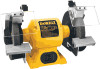
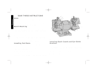
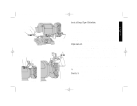
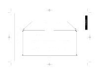
DW756,758/385498 8/20/01 7:43 AM Page 2 English SAVE THESE INSTRUCTIONS Motor Be sure your power supply agrees with the nameplate marking. 120 Volts, 50/60 Hz means alternating current only should be used to operate this tool.A power decrease of more than 10% will cause loss of power and overheating. All DeWalt tools are factory tested; if this tool does not operate, check the power supply Bench Mounting 1. The grinder should be unplugged. 2. Remove the drilling template from this manual (pg. 5) and place it in position of the bench. Check for the availability of power for the grinder. Tape the template to the bench. 3. Using a center punch, transfer the hole centers for drilling. 4. Drill appropriate sized holes. 5. Insert 1/4" (6mm) Hex head bolts through washers and the holes. You may want to use washers on the underside of the bench as well. 6. Tighten the nuts. Do not overtighten. Allow the rubber feet to absorb the vibration when the grinder is running. Installing Tool Rests TURN OFF POWER AND DISCONNECT FROM POWER SUPPLY. Your grinder includes a hex wrench, attached to the right of the On/Off switch. Use this wrench when installing the tool rest brackets, tool rest and eye shield brackets. First install the tool rest brackets, as shown in Fig. 2. Next attach the tool rests. Use the bolts, washers, spacers and lock nuts from the plastic bag to secure the brackets and tool rests in place. NOTE: There is a left and right tool rest. When in actual use, the tool rests should be adjusted to within 1/8" of the grinding wheel or other accessory being used. FIG. 1 EYE SHIELD BRACKETS SPARK GUARDS EYE SHIELDS COARSE GRINDING WHEEL (36 GRIT) TOOL RESTS MEDIUM GRINDING WHEEL (60 GRIT) SWITCH (ON - OFF) DW756 - 6" Bench Grinder 1/2"(13mm) Arbor, 3450 RPM DW758 - 8" Heavy Duty Bench Grinder 5/8"(16mm) Arbor, 3600 RPM Installing Spark Guards and Eye Shield Brackets TURN OFF TOOL AND DISCONNECT FROM POWER SUPPLY The combination spark guard and eye shield brackets are assembled and in a plastic bag. They are identified L for left and R for right. Refer to Figure 3 to install them to the bench grinder using the two screws in the wheel guard (in some cases these screws will be in the plastic bag). Adjust the edge of the spark guard to within 1/16" of the grinding wheel or other accessory as shown in the figure. Tighten the two screws securely. 2
-
 1
1 -
 2
2 -
 3
3 -
 4
4 -
 5
5 -
 6
6 -
 7
7 -
 8
8 -
 9
9 -
 10
10 -
 11
11 -
12
-
13
-
14
-
15
-
16
-
17
-
18
-
19
-
20
-
21
-
22
-
23
-
24
-
25
-
26
-
27
 |
 |