Dewalt DWE74911 Instruction Manual - Page 5
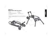
ASSEMBLY, Assembling Stand Frame Halves Fig. 2, Attaching the Wheels, and Axle Fig. 3, Attaching - table saw stand
 |
View all Dewalt DWE74911 manuals
Add to My Manuals
Save this manual to your list of manuals |
Page 5 highlights
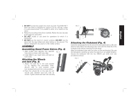
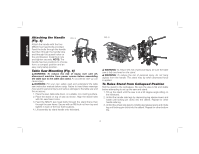
English • DO NOT exceed the weight this stand can hold. The DWE74911 table saw stand is designed to support 150 lbs. (68 kgs.) safely in a work environment. It is unsafe to climb, sit or stand on the stand. • Follow the mounting instructions carefully. Fasten the saw securely to the stand as instructed. • DO NOT modify or use stand for operations for which it is unintended. • DO NOT use the stand on uneven surfaces. DO NOT use the stand with the legs folded and stand sitting on the ground. The stand is designed to be used on a flat, stable surface. ASSEMBLY Assembling Stand Frame Halves (Fig. 2) 1. Slide smaller tube diameter into opposite FIG. 2 tube side as shown until holes align. 2. Install M6x12 pan head bolts until tight on both sides. Attaching the Wheels and Axle (Fig. 3) 1. Attach the axle (A) to the end bracket (J) by aligning the pre-drilled holes. Secure axle to end bracket using two carriage bolts and lock nuts provided. 2. Place the wheels (B) on the axle (A) and secure with washers and lock nuts as shown. Tighten wheel and axle nuts securely. FIG. 3 B B AJ Attaching the Kickstand (Fig. 4) Insert the tube plugs (K) into the end of the kickstand tube (L). Be sure that the holes (M) in the tube plugs are in line with the holes (N) in the kickstand tube before inserting the tube plugs. Align the kickstand holes with the holes on the end bracket. Be sure the kickstand is pointing up when the stand is in an upright position. Secure the kickstand with the four M8x45 pan bolts and nuts provided as shown. FIG. 4 N N K M L M K 3
-
 1
1 -
 2
2 -
 3
3 -
 4
4 -
 5
5 -
 6
6 -
 7
7 -
 8
8 -
 9
9 -
 10
10 -
 11
11 -
12
-
13
-
14
-
15
-
16
-
17
-
18
-
19
-
20
-
21
-
22
-
23
-
24
 |
 |
