Dewalt DWE74911 Instruction Manual - Page 6
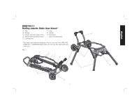
Attaching the Handle, Fig. 5, Table Saw Mounting Fig. 6, To Raise Stand from Collapsed Position - rolling table saw
 |
View all Dewalt DWE74911 manuals
Add to My Manuals
Save this manual to your list of manuals |
Page 6 highlights
English Attaching the Handle FIG. 5 (Fig. 5) Attach the handle with the four M8x45 hex head bolts provided. Feed the bolts through the handle feet then through the handle tube and through the gusset holes on the end bracket. Install four nuts and tighten securely. NOTE: The handle has two positions to choose from: a compact position and an easy carry/setup position. Table Saw Mounting (Fig. 6) WARNING: To reduce the risk of injury, turn unit off, disconnect machine from power source before assembling the table saw to the table saw stand. An accidental start-up can cause injury. WARNING: For your own safety, read and understand the table saw instruction manual before using. Failure to heed these warnings may result in personal injury and serious damage to the table saw and the accessory. 1. Place the saw, table side down, on a stable, non-marring surface. 2. Place the stand on top of saw as shown. Align the stand holes with the saw frame holes. 3. Feed the M8x75 pan head bolts through the stand frame then through the saw frame. Secure with an M8 lock nut from top and tighten in each of the four hole locations. 4. Lift assembly by stand handle onto kickstand. FIG. 6 WARNING: To reduce the risk of personal injury, be sure the table saw is fully anchored on the stand. WARNING: To reduce the risk of personal injury, do not hang objects from the handle. The stand may tip when downward force is applied. To Raise Stand from Collapsed Position Roll the stand to the workspace. Be sure the area is flat and stable before attempting to set up the saw and stand. 1. Tilt up the stand until the saw is at a 90 degree angle sitting on the kickstand. 2. Unfold the handle side legs by depressing leg release levers and rotate until locking pin clicks into the detent. Repeat for other handle side leg. 3. Unfold the wheel side legs by rotating leg release levers and rotate leg until locking pin clicks into the detent. Repeat for other bottom leg. 4
-
 1
1 -
 2
2 -
 3
3 -
 4
4 -
 5
5 -
 6
6 -
 7
7 -
 8
8 -
 9
9 -
 10
10 -
 11
11 -
 12
12 -
13
-
14
-
15
-
16
-
17
-
18
-
19
-
20
-
21
-
22
-
23
-
24
 |
 |
