EVGA 131-GT-E767-TR User Guide
EVGA 131-GT-E767-TR Manual
 |
View all EVGA 131-GT-E767-TR manuals
Add to My Manuals
Save this manual to your list of manuals |
EVGA 131-GT-E767-TR manual content summary:
- EVGA 131-GT-E767-TR | User Guide - Page 1
User's Guide EVGA X58 SLI3 Motherboard - EVGA 131-GT-E767-TR | User Guide - Page 2
in the Kit 7 Intentions of the Kit 7 EVGA X58 SLI3 Motherboard 9 Motherboard Specifications 9 Unpacking and Parts Descriptions 11 Unpacking ...11 Equipment ...11 EVGA X58 SLI3 Motherboard 12 Hardware Installation 15 Safety Instructions 15 Preparing the Motherboard 16 Installing the CPU 16 - EVGA 131-GT-E767-TR | User Guide - Page 3
pin ATX 12V Power (PW12 22 Connecting SATA Cables 22 Connecting Internal Headers 23 Front Panel Header 23 IEEE1394a (Firewire 24 USB Headers BIOS 32 Enter BIOS Setup 33 Main Menu...33 Standard CMOS Features Menu 36 Date and Time...37 SATA Channel...37 Halt On ...39 Memory ...39 Advanced BIOS - EVGA 131-GT-E767-TR | User Guide - Page 4
42 Security Option 42 Integrated Peripherals Menu 43 OnChip PATA/SATA Device 44 Onboard Device 45 USB Device Settings 46 Power Management Setup Menu 47 ACPI Function 48 Soft-Off by PWR-BTTN 48 Wake-Up by PCI Card 48 USB KB Wake-Up From S3 48 Resume by Alarm 48 POWER ON Function 49 - EVGA 131-GT-E767-TR | User Guide - Page 5
PC Health Status Menu 53 SmartFan Function 54 Frequency/Voltage Control Menu 55 Memory Feature 56 Voltage Control 58 CPU Feature ...59 Installing Drivers and Software 62 Windows XP/Vista Driver Installation 62 Appendix A. POST Codes for the EVGA X58 SLI3 Motherboard 63 - EVGA 131-GT-E767-TR | User Guide - Page 6
List of Figures Figure 1. EVGA X58 SLI3 Motherboard Layout 13 Figure 2. Chassis Back Panel Connectors 14 Figure 3. PW1 Motherboard Connector 21 Figure 4. BIOS CMOS Setup Utility Main Menu 34 Figure 5. Standard CMOS Features Menu 36 Figure 6. Advanced BIOS Features Menu 40 Figure 7. Integrated - EVGA 131-GT-E767-TR | User Guide - Page 7
the EVGA X58 SLI3 Motherboard. This board is designed to take the already excellent performance of the EVGA lineup and push it into the future by adding support for SATA 6Gbps and USB 3.0. As always with this board you also get the added bonus of EVGA's industry leading 24/7 technical support in - EVGA 131-GT-E767-TR | User Guide - Page 8
When replacing a motherboard in a system case, you will need to reinstall an operating system even though the current Hard Disk Drive may already have an operating system. - EVGA 131-GT-E767-TR | User Guide - Page 9
innovative NVIDIA® SLI® technology for enhanced system performance. Motherboard Specifications Size ATX form factor of 12 inch x 9.6 inch Microprocessor support Intel Core i7 processor Operating systems: Supports Windows XP, Vista, and Win 7 32/64 Bit Contains INTEL X58 and ICH10R chipset - EVGA 131-GT-E767-TR | User Guide - Page 10
data transfer rate Six SATA II connectors from south bridge with support for RAID 0, RAID 1, RAID 10 and RAID 5 Supports hot plug and NCQ (Native Command Queuing ) Two (2) SATA3 6Gbps onboard ports from Marvell 88SE9128 Chipset Onboard LAN Integrated LAN port Supports 10/100/1000 Mbit - EVGA 131-GT-E767-TR | User Guide - Page 11
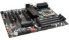
are included with the EVGA X58 SLI3 Motherboard. The EVGA X58 SLI3 Motherboard This PCI Express motherboard contains the Intel X58 and ICH10R chipset and is SLI-ready for both 2-Way and 3-Way SLI configurations. 1 - Visual Guide Helps to quickly and visually guide you through the hardware - EVGA 131-GT-E767-TR | User Guide - Page 12
which allows for 3-Way SLI. 1 - Installation CD Contains drivers and software needed to setup the motherboard. EVGA X58 SLI3 Motherboard The EVGA X58 SLI3 Motherboard with the Intel X58 and ICH10R chipset is a PCI Express, SLI-ready motherboard. Figure 1 shows the motherboard and Figures 2 shows the - EVGA 131-GT-E767-TR | User Guide - Page 13
15 14 13 4 4 11 22 23 6 1 2 12 3 10 9 8 1. CPU Socket 1366 2. Intel X58 Chipset 3. DDR3 DIMM Slots 1 - 6 4. Fan Connectors 5. 24-Pin ATX Power Connector 6. 8-pin ATX_12V Power Connector 7. Intel ICH10R Chipset 8. SATA II Connectors 9. Debug LED Display - CPU Temperature Monitor 10. Front Panel - EVGA 131-GT-E767-TR | User Guide - Page 14
1 5 2 3 4 2 1. PS/2 Keyboard Port 2. USB 2.0 Ports (Eight) 3. Clear CMOS Button 4. USB 3.0 Ports (two) 5. LAN Port with LEDs to indicate status: Activity LED Status Off Blinking (Green) Description No data transmission Data transmission 2 2 6 Speed/Link LED Status - EVGA 131-GT-E767-TR | User Guide - Page 15
This section will guide you through the installation of the motherboard. The topics covered in this section are: Preparing the motherboard Installing the CPU Installing the CPU fan Installing the memory Installing the motherboard Connecting cables Safety Instructions To reduce the - EVGA 131-GT-E767-TR | User Guide - Page 16
the processor only by the edges and do not touch the bottom of the processor. Use the following procedure to install the CPU onto the motherboard: 1. Unhook the socket lever by pushing down and away from the socket. 2. Put your finger on the tail of the load plate and press down - EVGA 131-GT-E767-TR | User Guide - Page 17
is complete. Align notches with notches on the CPU Installing the CPU Fan There are many different fan types that can be used with this motherboard. Follow the instruction that came with you fan assembly. Be sure that the fan orientation is correct for your chassis type and your fan assembly. - EVGA 131-GT-E767-TR | User Guide - Page 18
Installing System Memory (DIMMs) Your new motherboard has six 240-pin slots for DDR3 memory. These slots support 1GB, 2GB, 4GB DDR3 DIMMs. There must be at least one memory bank populated to ensure normal operation. Use the following the recommendations for installing - EVGA 131-GT-E767-TR | User Guide - Page 19
Fan assembly is aligned with the vents on the covers. This will depend on the system case being used. Installing the I/O Shield The motherboard kit comes with an I/O shield that is used to block radio frequency transmissions, protects internal components from dust and foreign objects, and promotes - EVGA 131-GT-E767-TR | User Guide - Page 20
vents according to the fan assembly instruction. 5. Secure the motherboard with a recommended minimum of nine motherboard. This will include: Power Connections 24-pin ATX power (PW1) 8-pin ATX 12V power (PW12) Internal Headers Front panel IEEE 1394a USB Headers Audio SATA II SATA - EVGA 131-GT-E767-TR | User Guide - Page 21
USB 2.0 24-pin ATX Power (PW1) PW1 is the main power supply connector located along the edge of the board next to the DIMM slots. Make sure that the power supply cable and pins are properly aligned with the connector on the motherboard. Firmly plug the power supply cable into the connector and - EVGA 131-GT-E767-TR | User Guide - Page 22
controlled by the South Bridge Chipset. These connection points support RAID 0, RAID 1, RAID 5 and RAID 10 configurations. There are also two (2) SATA 6Gbps Connectors on the motherboard. Connection points SATA6 and SATA7 Which connect to SATA 6Gbps capable devices and allow a maximum transfer rate - EVGA 131-GT-E767-TR | User Guide - Page 23
Connecting Internal Headers Front Panel Header The front panel header on this motherboard is one connector used to connect the following four cables. (see Table 2 for pin definitions): PWRLED Attach the front panel power LED cable to these - EVGA 131-GT-E767-TR | User Guide - Page 24
cases are equipped with the front panel option). 2. Connect the end of the cable(s) to the IEEE1394a headers on the motherboard. Table 3. IEEE 1394a Connector Pins Connector IEEE 1394a Connector 10 9 8 7 6 5 4 3 2 1 Pin Signal 1 TPA+ 2 TPA- 3 GND 4 GND 5 TPB+ 6 TPB- 7 +12V - EVGA 131-GT-E767-TR | User Guide - Page 25
all chassis are equipped with the front panel option). 2. Connect the end of the cable to the USB 2.0 header on the motherboard. Table 4. USB 2.0 Header Pins Connector Pin USB 2.0 Header Connector 1 3 5 7 9 Pin 2 4 6 8 10 Signal 5V_DUAL DD+ GND Empty Signal 5V_DUAL DD+ GND No Connect - EVGA 131-GT-E767-TR | User Guide - Page 26
HD audio standard and provides two kinds of audio output choices: the Front Audio, the Rear Audio. The front Audio supports re-tasking function. Table 5. Front Audio Connector Connector Front Audio Connector 10 9 8 7 6 5 4 3 2 1 Pin Signal 1 PORT1_L 2 AUD_GND 3 PORT1_R 4 PRECENCE_J - EVGA 131-GT-E767-TR | User Guide - Page 27
Fan Connections There are six fan connections on the motherboard. The fan speed can be detected and viewed in the PC Health Status section of can be either a 3-pin or a 4-pin connector. Connect a 3-pin connector to pins 1, 2, and 3 on the motherboard connector. CPU Fan Ground +12V Sense Control - EVGA 131-GT-E767-TR | User Guide - Page 28
Expansion Slots The EVGA X58 SLI3 Motherboard contains six (6) expansion slots, five (5) PCI Express slots and one (1) PCI slots. For a full list of PCI Express graphic cards supported by this motherboard, visit: www.EVGA.com/Products 6 5 4 3 2 1 Slot Listing 1 - PCI-E 2.0 x8/x16 - Slot 1 ( - EVGA 131-GT-E767-TR | User Guide - Page 29
PCI Slots The PCI slot supports many expansion cards such as a LAN card, USB card, SCSI card and other cards reserved for Graphic Cards and PCI Express x1 and x4 devices. The design of this motherboard supports multiple Graphic Card technology. When installing a PCI Express Graphic Card, be sure the - EVGA 131-GT-E767-TR | User Guide - Page 30
the system, or clear the CMOS. Clear CMOS Button The motherboard uses the CMOS RAM to store all the set parameters. The CMOS can be cleared These buttons allow for easy debugging and testing of the system during troubleshooting situations. The POWER button with LED indicates the system's status. - EVGA 131-GT-E767-TR | User Guide - Page 31
to show why the system may be failing to boot. It is useful during troubleshooting situations. This Debug LED will also display current CPU temperatures after the system will remain on as long as the motherboard is receiving constant power. POWER LED (YELLOW) DIMM LED (GREEN) STANDBY LED (BLUE) - EVGA 131-GT-E767-TR | User Guide - Page 32
to change the system settings through the BIOS Setup menus. Descriptions of the BIOS parameters are also provided. This section includes the following information: Enter BIOS Setup Main Menu Standard CMOS Features Advanced BIOS Features Integrated Peripherals Power Management Setup PnP - EVGA 131-GT-E767-TR | User Guide - Page 33
the arrow keys to position the selector in the option you choose. To go back to the previous menu, press Esc. Note: that on the BIOS screens all data in white is for information only, data in yellow is changeable, data in blue is non-changeable, and data in a red box - EVGA 131-GT-E767-TR | User Guide - Page 34
this menu to set up the basic system configuration. Advanced BIOS Features Use this menu to set up the advanced system features and boot sequence. Integrated Peripherals Use this menu to set up onboard peripherals such as IDE, RAID, USB, LAN, and MAC control. Power Management Setup Use this - EVGA 131-GT-E767-TR | User Guide - Page 35
Optimized defaults system settings. Set Supervisor Password/Set User Password Use this command to set, change, and disable the password used to access the BIOS menu. Save & Exit Setup Use this command to save settings to CMOS and exit setup. Exit Without Saving Use this command to abandon all - EVGA 131-GT-E767-TR | User Guide - Page 36
Utility Standard CMOS Features Date (mm:dd:yy) Time (hh:mm:ss) Thu, Oct 23 2008 12 : 48: 23 Item Help SATA 0 SATA 1 SATA 2 SATA 3 SATA 4 SATA 5 Halt On Base Memory Extended Memory Total Memory [None] [None] [None] [None] [None] [None] [All , But Keyboard] 640K 1047552K 1048576K - EVGA 131-GT-E767-TR | User Guide - Page 37
Time (hh:mm:ss) Sat, Jul 01 2006 14 : 48: 43 SATA Channel Use these functions to detect and configure the SATA channels. Select a channel and press Enter to display the SATA sub-menu. SATA 0 SATA 1 SATA 2 SATA 3 SATA 4 SATA 5 [None] [None] [None] [None] [None] [None] Press ENTER to - EVGA 131-GT-E767-TR | User Guide - Page 38
] IDE Channel 0 Slave Access Mode Capacity Cylinder Head Precomp Landing Zone Sector [Manual} [CHS] 0 MB .....0 [ 0] [ 0] [ 0] [ 0] Press ENTER to display sub-menu or enter number manually Cylinder Min= 0 The BIOS supports the following HDD Max=65535 Access Modes: CHS Key in a DEC number - EVGA 131-GT-E767-TR | User Guide - Page 39
the changes and return to the Standard CMOS Features menu. Halt On [All , But Keyboard] Press ENTER to display sub-menu All Errors Whenever the BIOS detects a nonfatal error, the system stops and prompts you. No Errors System boot does not stop for any detected errors. Halt On All Errors - EVGA 131-GT-E767-TR | User Guide - Page 40
to display the sub-menus. Phoenix - AwardBIOS CMOS Setup Utility Advanced BIOS Features Hard Disk Boot Priority CD-ROM Boot Priority First Boot F1:General Help F5:Previous Values F7:Optimized Defaults Figure 6. Advanced BIOS Features Menu Note: That all data in white is for information only - EVGA 131-GT-E767-TR | User Guide - Page 41
Hard Disk Boot Priority Use this option to select the priority for HDD startup. Press Enter to see the list of bootable devices in your system. Use the arrow keys to go to the various devices. Then use the + or - keys to move the device priority up or down in the list. To go back to the previous - EVGA 131-GT-E767-TR | User Guide - Page 42
Boot Other Device With the option set to Enable, the system boots from some other device if the first/second/third boot devices fail. Boot Up NumLock Status This option allows you to select the power-on state of NumLock. Select On to activate the keyboard NumLock when the system is started. Select - EVGA 131-GT-E767-TR | User Guide - Page 43
menu and press Enter to display the Integrated Peripherals menu. Phoenix - AwardBIOS CMOS Setup Utility Integrated Peripherals Onboard PATA/SATA Device Onboard Device USB Device Setting [Press Enter] [Press Enter] [Press Enter] Item Help Main Level Move Enter:Select +/-/PU/PD:Value - EVGA 131-GT-E767-TR | User Guide - Page 44
the OnChip PATA/SATA Device menu. SATA Mode LEGACY Mode Support [IDE] [Disabled] SATA 3.0 Storage Controlle [Enabled] SATA Mode This is allows you set the onboard Serial SATA mode. IDE: Use the SATA hard disk drivers as Parallel ATA storage devices. RAID: Create a RAID 0, 1, 10 and - EVGA 131-GT-E767-TR | User Guide - Page 45
Onboard Device Press Enter to display the Onboard Device menu. PE5 Slot (PCIE x1) Realtek GigaLan (LAN1) [Auto] [Auto] PE4 Slot (PCIE x1) Realtek Lan PXE Boot ROM TI 1394 Setting High Definition Audio P80 Show CPU Temp. [Auto] [Disabled] [Enabled] [Enabled] [Enabled] PE5 Slot (PCIE x1) Use - EVGA 131-GT-E767-TR | User Guide - Page 46
. Options are Full/Low Speed and High Speed. USB Keyboard Function Use this function to enable or disable support for USB keyboard under DOS. USB Mouse Function Use this function to enable or disable support for USB mouse under DOS USB Storage Function Use this function to enable or disable - EVGA 131-GT-E767-TR | User Guide - Page 47
Type Run VGABIOS if S3 Resume Soft-Off by PWR-BTTN Wake-Up by PCI Card USB KB Wake-Up From S3 Resume by Alarm x Day of Month Alarm x Time (hh:mm:ss) Alarm HPET Support HPET Mode POWER ON Function x Hot Key Power On PWRON After PWR-Fail [Enabled] [S3(STR - EVGA 131-GT-E767-TR | User Guide - Page 48
the VGA BIOS when resuming USB keyboard device to wake-up the system from S3 state. Resume by Alarm This function on the Power Management Setup menu allows you to enable or disable the Power-on by alarm function. Set to [Disable] to prevent poweron by alarm. When set to [Enable], you can manually - EVGA 131-GT-E767-TR | User Guide - Page 49
Day of Month Alarm Time (hh:mm:ss) Alarm [ 0] [0 : 0 : 0] To enter a day or time, use the Page Up and Page Down keys to scroll through numbers or enter the number using the keyboard number or the + and - keys. POWER ON Function This function on the Power Management Setup menu allows you to define - EVGA 131-GT-E767-TR | User Guide - Page 50
PnP/PCI Configuration Menu Select PnP/PCI Configuration from the CMOS Setup Utility menu and press Enter to display the PnP/PCI Configuration menu. Phoenix - AwardBIOS CMOS Setup Utility PnP/PCI Configuration Init Display First Reset Configuration [PCI Slot] [Disabled] Item Help Resources - EVGA 131-GT-E767-TR | User Guide - Page 51
select IRQ, DMA, and memory base address fields. Select [Auto(ESCD)] if you want the BIOS to automatically populate these fields. If you select [Manual] so you can assign the resources, IRQ Resources is enabled for input. Resources Controlled By [Auto(ESCD)] x IRQ Resources Press Enter Resources - EVGA 131-GT-E767-TR | User Guide - Page 52
with the plug-and-play standard, whether designed for PCI or ISA Bus architecture. PCI/VGA Palette Snoop This item is designed to overcome problems that may be caused by some nonstandard VGA cards.. INT Pin 1/2/3/4/5/6/7/8 Assignment This function on the PnP/PCI Configuration menu allows you to set - EVGA 131-GT-E767-TR | User Guide - Page 53
PC Health Status Menu Select PC Health Status from the CMOS Setup Utility menu and press Enter to display the PC Health Status menu. Phoenix - AwardBIOS CMOS Setup Utility PC Health Status SmartFan Function VCC 3.3V CPU Vcore DIMM Voltage CPU VTT Voltage IOH Vcore VCC +12V 3VSB VBT CPU - EVGA 131-GT-E767-TR | User Guide - Page 54
menu to control the speed of the various fans on the motherboard. Set CPU fan speed to [SmartFan] when you want the speed of the fans automatically controlled based on temperature. To set the fan speed to a constant rate, select [Manual] and then enter the speed from 0% to 100%. Set the desired - EVGA 131-GT-E767-TR | User Guide - Page 55
EVGA X58 SLI3 Motherboard Frequency/Voltage Control Menu Select Frequency/Voltage Control from the CMOS Setup Utility menu and press Enter to display the Frequency/Voltage Control menu. Phoenix - - EVGA 131-GT-E767-TR | User Guide - Page 56
Memory Feature Select Memory Feature from the Frequency/Voltage Control menu and press Enter to display the Memory Feature menu. Phoenix - AwardBIOS CMOS Setup Utility Memory Feature Memory SPD [Standard] Memory Control Setting [Disabled] Memory Frequency [Auto] Target memory Frequency 1067 - EVGA 131-GT-E767-TR | User Guide - Page 57
Rank Interleave Setting This function is allows you to select the Rank Interleave Setting. The options are 1 way, 2 way and 4 way. tCL Setting This function is set the CAS latency. The options are 0 through 18. tRCD Setting This function is set the RAS to CAS Delay for Read/Write commands to - EVGA 131-GT-E767-TR | User Guide - Page 58
/PD:Value F10:Save ESC:Exit F1:General Help F5:Previous Values F7:Optimized Defaults Figure 13. Voltage Control EVGA VDroop Control EVGA VDroop control is a safety measure by motherboards to protect the CPU. Select [With VDroop] to calibrate CPU VDroop or select [Without VDroop] to disable this - EVGA 131-GT-E767-TR | User Guide - Page 59
Page Down keys to select a voltage or select [Auto] to automatically set the voltage. ICH VCore This function defines the core voltage level for the Intel ICH chip. Use the Page Up and Page Down keys to select a voltage or select [Auto] to automatically set the voltage. CPU Feature Select CPU - EVGA 131-GT-E767-TR | User Guide - Page 60
options are Enabled and Disabled. Turbo Mode Function Use this function to enable the Intel Turbo Mode Function. The options are Enabled and Disabled. CxE Function This function allows you to select the lowest C state supported according as CPU and MB. The options are Auto, Disabled, C1, C1E, C3 - EVGA 131-GT-E767-TR | User Guide - Page 61
the additional hardware capabilities provided by Intel Virtualization Technology. Logical Processor Setting Intel HT Technology This function is allows you to enable the Intel HT Technology. The options are Enabled to select the QPI Frequency. The options are Auto, 4.800 GT/s, 5.866 GT/s and 6.400 - EVGA 131-GT-E767-TR | User Guide - Page 62
with the EVGA X58 SLI3 Motherboard contains the following software and drivers: Chipset Drivers Audio drivers RAID drivers LAN Drivers Matrix Storage EVGA E-LEET Adobe Acrobat Reader User's Manual Windows XP/Vista Driver Installation 5. Insert the Intel X58 Express installation - EVGA 131-GT-E767-TR | User Guide - Page 63
Appendix A. POST Codes for the EVGA X58 SLI3 Motherboard This section provides the Award POST Codes (Table 6) for the EVGA X58 SLI3 Motherboard during system boot up. The POST Codes are displayed on the Debug LED readout located directly onboard the motherboard. This Debug LED will also display - EVGA 131-GT-E767-TR | User Guide - Page 64
Award POST Codes Code Name 0D Reserved Description 0E CheckSum Check Check the integrity of the ROM,BIOS and message 0F Reserved 10 Autodetect EEPROM Check Flash type and copy flash write/erase routines 11 Reserved 12 Test CMOS Test and Reset CMOS - EVGA 131-GT-E767-TR | User Guide - Page 65
38 Reserved 39 Test DMA Page Registers 3A Reserved 3B Reserved 3C Test Timer 3D Reserved 3E Test 8259-1 Mask 3F Reserved Description Setup BIOS DATA AREA (BDA) Chipset programming and CPU Speed detect Initialize Video Test Video Memory and display Logos Early Keyboard Reset Test DMA channel 0 Test - EVGA 131-GT-E767-TR | User Guide - Page 66
Reserved 4B Reserved 4C Reserved 4D Reserved 4E Init APIC 4F Reserved 50 USB init 51 Reserved 52 Memory Test 53 Reserved 54 Reserved 55 CPU 640K and extended memory above 1MB. Initialize APIC and set MTRR Initialize USB controller Test all memory of memory above 1MB using Virtual 8086 mode, page - EVGA 131-GT-E767-TR | User Guide - Page 67
PS2 Mouse port ACPI sub-system initializing Initialize cache controller Enter setup check and autoconfiguration check up Initialize floppy disk drive Install FDD and setup BIOS data area parameters - EVGA 131-GT-E767-TR | User Guide - Page 68
check 80 Reserved 81 Reserved 82 Security Check 83 Write CMOS 84 Display PNP 85 USB Final Init 86 Reserved 87 Reserved 88 Reserved 89 Setup ACPI tables 8A Reserved Write all CMOS values back to RAM and clear screen. Display PNP devices Final USB initialization Setup ACPI tables Scan for Option ROMs - EVGA 131-GT-E767-TR | User Guide - Page 69
FF Program MCP Setup Pages Boot Description Enable Parity Check Enable IRQ12 if mouse present Detect and store boot partition head and cylinders values in RAM Final init for last micro details before boot Set NumLock status according to Setup Set low stack Boot via INT 19h. Read/Write CPU - EVGA 131-GT-E767-TR | User Guide - Page 70
EVGA Glossary of Terms ACPI - Advanced Configuration and Power Interface AFR - Alternate Frame Rendering APIC - Advanced Programmable Interrupt Controller BIOS - Basic Input Output System CD-ROM - Compact Disc Read-Only Memory CMOS - Complementary Metal-Oxide Semiconductor CPU - Central Processing - EVGA 131-GT-E767-TR | User Guide - Page 71
Device Engineering Council LAN - Local Area Network LCD - Liquid Crystal Display LGA - Land Grid Array LN2 - Liquid Nitrogen Cooling MAC - Media Data Rate QPI - Quick Path Interconnect RAID - Redundant Array of Inexpensive Disks RGB - Red Green Blue SATA - Serial Advanced Technology Attachment SB - - EVGA 131-GT-E767-TR | User Guide - Page 72
SLI - Scalable Link Interface SPD - Serial Presence Detect SPDIF - Sony/Philips Digital Interconnect Format SPP - System Platform Processors TCP/IP - Transmission Control Protocol/Internet Protocol USB - Universal Serial Bus VDroop - V-core Voltage Drop VGA - Video Graphics Array
-
 1
1 -
 2
2 -
 3
3 -
 4
4 -
 5
5 -
 6
6 -
 7
7 -
8
-
9
-
10
-
11
-
12
-
13
-
14
-
15
-
16
-
17
-
18
-
19
-
20
-
21
-
22
-
23
-
24
-
25
-
26
-
27
-
28
-
29
-
30
-
31
-
32
-
33
-
34
-
35
-
36
-
37
-
38
-
39
-
40
-
41
-
42
-
43
-
44
-
45
-
46
-
47
-
48
-
49
-
50
-
51
-
52
-
53
-
54
-
55
-
56
-
57
-
58
-
59
-
60
-
61
-
62
-
63
-
64
-
65
-
66
-
67
-
68
-
69
-
70
-
71
-
72
 |
 |

User
’s
Guide
EVGA X58 SLI3 Motherboard