EVGA 132-CK-NF79-TR User Manual - Page 17
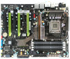
EVGA nForce 790i Ultra SLI Motherboard Layout
 |
View all EVGA 132-CK-NF79-TR manuals
Add to My Manuals
Save this manual to your list of manuals |
Page 17 highlights
nForce 790i Ultra SLI Motherboard 21 21 23 23 24 25 26 22 22 22 20 27 28 19 18 11 1 2 29 17 16 3 16 4 15 14 13 12 11 10 9 8 11 7 6 1. CPU Socket 11. Fan connectors 2. nForce 790i Ultra SLI heatpipe 12. Serial-ATA (SATA) connectors 3. CPU fan connector 13. Front panel connector 4. DDR3 DIMM slots 0 - 3 14. Serial connector 5. 24-pin ATX power connector 15. Jumper 6. IDE connector 16. USB headers 7. Serial-ATA (SATA) connectors 17. 1394a connector 8. FDD connector 18. Power button 9. NVIDIA MCP (passive heat sink) 19. Reset Button 10. Diagnostic code display 20. Front panel Audio connector 5 21. PCI slots 22. PCI Express x16 slots (SLI) 23. PCI Express x1 slot 24. SATA connector 25. Backpanel connectors (Figure 2) 26. Heat dissipater 27. 8-pin ATX_12V power connector 28. MCP/SPP fan connector (not used) 29. Motherboard battery Figure 1. EVGA nForce 790i Ultra SLI Motherboard Layout EVGA Corporation 6 January 11, 2008 | DU-03751-001_v01
-
 1
1 -
2
-
3
-
4
-
5
-
6
-
7
-
8
-
9
-
10
-
11
-
 12
12 -
 13
13 -
 14
14 -
 15
15 -
 16
16 -
 17
17 -
 18
18 -
 19
19 -
 20
20 -
 21
21 -
 22
22 -
23
-
24
-
25
-
26
-
27
-
28
-
29
-
30
-
31
-
32
-
33
-
34
-
35
-
36
-
37
-
38
-
39
-
40
-
41
-
42
-
43
-
44
-
45
-
46
-
47
-
48
-
49
-
50
-
51
-
52
-
53
-
54
-
55
-
56
-
57
-
58
-
59
-
60
-
61
-
62
-
63
-
64
-
65
-
66
-
67
-
68
-
69
-
70
-
71
-
72
-
73
-
74
-
75
-
76
-
77
-
78
-
79
-
80
-
81
-
82
-
83
-
84
-
85
-
86
-
87
-
88
-
89
-
90
-
91
-
92
-
93
-
94
-
95
-
96
-
97
-
98
-
99
-
100
-
101
-
102
-
103
-
104
-
105
-
106
-
107
-
108
-
109
-
110
-
111
-
112
-
113
-
114
-
115
-
116
-
117
-
118
-
119
-
120
-
121
-
122
-
123
-
124
-
125
-
126
-
127
 |
 |
