Edimax AR-7211A V2 Manual - Page 9
Hardware Installation
 |
View all Edimax AR-7211A V2 manuals
Add to My Manuals
Save this manual to your list of manuals |
Page 9 highlights
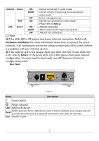
2. Hardware Installation Step 1. Connect the ADSL line Connect the Line interface of the device to the Modem interface of a splitter using a telephone cable. Connect a telephone to the Phone interface of the splitter using a telephone cable. Connect the Line interface of the splitter to your existing, incoming line. The splitter has three interfaces: Line: Connect to a wall phone jack (RJ-11 jack). Modem: Connect to the ADSL jack of the device. Phone: Connect to a telephone set. Step 2. Connect the router to your LAN network Connect the LAN interface of the router to your PC, Hub or Switch using an Ethernet cable (MDI/MDIX). Note: Use twisted-pair Ethernet cables to connect the router to a hub or switch. Step 3. Connect the power adapter to the router Plug one end of the power adapter into a wall outlet and connect the other end to the 5V interface of the device. The following diagrams show how to correctly connect the router, PC, splitter and the telephone sets under two different configurations: Configuration 1 0 shows the correct connection of the router, PC, splitter and the telephone sets, with no telephone set placed before the splitter. 9
-
 1
1 -
2
-
3
-
 4
4 -
 5
5 -
 6
6 -
 7
7 -
 8
8 -
 9
9 -
 10
10 -
 11
11 -
 12
12 -
 13
13 -
 14
14 -
15
-
16
-
17
-
18
-
19
-
20
-
21
-
22
-
23
-
24
-
25
-
26
-
27
-
28
-
29
-
30
-
31
-
32
-
33
-
34
-
35
-
36
-
37
-
38
-
39
-
40
-
41
-
42
-
43
-
44
-
45
-
46
-
47
-
48
-
49
-
50
-
51
-
52
-
53
-
54
-
55
-
56
-
57
-
58
-
59
-
60
-
61
-
62
-
63
-
64
-
65
-
66
-
67
-
68
-
69
-
70
-
71
-
72
-
73
-
74
-
75
-
76
-
77
-
78
-
79
-
80
-
81
-
82
-
83
-
84
-
85
-
86
-
87
-
88
-
89
 |
 |