Electrolux E36GF76HPS Installation Instructions - Page 1
Electrolux E36GF76HPS - 36" Pro-Style Gas Range Manual
 |
View all Electrolux E36GF76HPS manuals
Add to My Manuals
Save this manual to your list of manuals |
Page 1 highlights
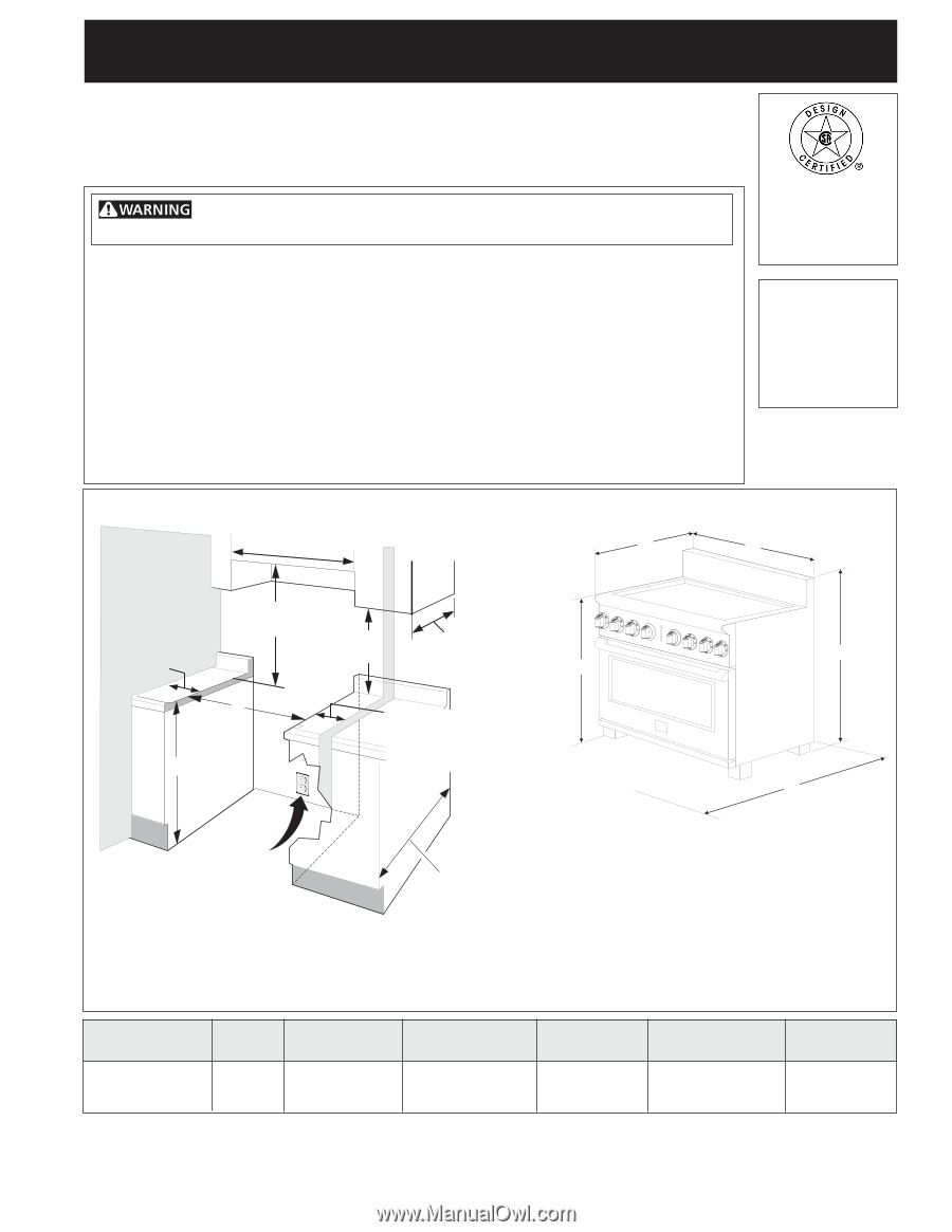
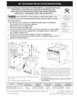
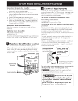
36" GAS RANGE INSTALLATION INSTRUCTIONS INSTALLATION AND SERVICE MUST BE PERFORMED BY A QUALIFIED INSTALLER. IMPORTANT: SAVE FOR LOCAL ELECTRICAL INSPECTOR'S USE. READ AND SAVE THESE INSTRUCTIONS FOR FUTURE REFERENCE. OBSERVE ALL GOVERNING CODES AND ORDINANCES. If the information in this manual is not followed exactly, a fire or explosion may result causing property damage, personal injury or death. FOR YOUR SAFETY: - Do not store or use gasoline or other flammable vapors and liquids in the vicinity of this or any other appliance. - WHAT TO DO IF YOU SMELL GAS: • Do not try to light any appliance. • Do not touch any electrical switch; do not use any phone in your building. • Immediately call your gas supplier from a neighbor's phone. Follow the gas supplier's instructions. • If you cannot reach your gas supplier, call the fire department. - Installation and service must be performed by a qualified installer, service agency or the gas supplier. Refer to your serial plate for applicable agency certification Note: For appliances installed in the state of Massachusetts see page 2. WALL 35 7/8" Min. (91.1 cm Min.) C B WALL See If there is a wall: note 7" Min. 18" Min. 13" Max. (17.8 cm Min) (45.7 cm Min.) (33 cm Max.) Left side D G F If there is a wall: 7" Min. (17.8 cm Min.) Right side A E Grounded Wall Outlet location NOTE: 28" (71.1 cm) minimum clearance between the cooktop and the bottom of the cabinet when the bottom 24" Min. of wood or metal cabinet is protected by not less than (61 cm Min.) 24 1/2" Max. 1/4" (0.64 cm) flame retardant millboard covered with (62.2 cm Max.) not less than No. 28 MSG sheet metal, 0.015" (0.4 mm) Do not pinch the power supply cord between the range and the wall. stainless steel, 0.024" (0.6 mm) aluminum, or 0.020" (0.5 mm) copper. 34" (86.4 cm) minimum clearance when the cabinet Do not seal the range to the side cabinets. is unprotected. A. HEIGHT B. WIDTH 41 5/8" (105.7 cm) Min. 35 7/8" 42 5/8" (108.3 cm) Max. (91.1 cm) C. DEPTH TO FRONT OF RANGE 27 ½" (69.9 cm) D. HEIGHT OF COOKTOP 35 3/4" (90.8 cm) Min. 36 3/4" (93.3 cm) Max. E. DEPTH WITH DOOR OPEN 47 3/8" (120.3 cm) F. HEIGHT OF COUNTERTOP 36" (91.4 cm) Standard 35 3/4" (90.8 cm) Min. G. MINIMUM CUTOUT WIDTH 36 1/16" (91.6 cm) Note: Wiring diagram for this model is enclosed in this booklet (see page 20). P/N 318201778 (0809) Rev. A Printed in United States English - pages 1-8; Español - páginas 9-16 Notes - pages 17-19; Wiring Diagram - page 20 1
-
 1
1 -
 2
2 -
 3
3 -
 4
4 -
 5
5 -
 6
6 -
 7
7 -
8
-
9
-
10
-
11
-
12
-
13
-
14
-
15
-
16
-
17
-
18
-
19
-
20
 |
 |