Electrolux E36GF76HPS Installation Instructions - Page 4
Gas Supply Installation - user manual
 |
View all Electrolux E36GF76HPS manuals
Add to My Manuals
Save this manual to your list of manuals |
Page 4 highlights
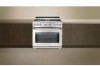
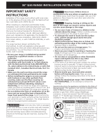
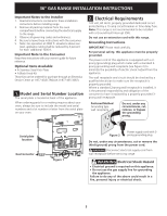
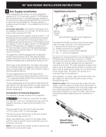
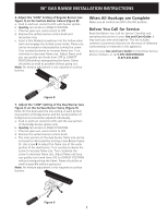
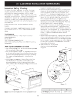
36" GAS RANGE INSTALLATION INSTRUCTIONS 3. Gas Supply Installation When shipped from the factory, this unit is designed to operate on 4"(10,16 cm) water column (1.0 kPa) Natural gas manifold pressure. A convertible pressure regulator is connected to the range manifold and MUST be connected in series with the gas supply line. The gas connector is located as shown on figure 1. It is accessible from front of the range. For proper operation, the maximum inlet pressure to the regulator should be no more than 14"(35,56 cm) of water column pressure (3.5 kPa). The inlet pressure to the regulator must be at least 1" (.25 kPa) greater than the regulator manifold pressure setting. The regulator is set for 4"(10,16 cm) water column (1.0 kPa) Natural gas manifold pressure; the inlet pressure must be at least 5"(12.60 cm) water column (1.25 kPa) Natural gas. For LP/Propane gas, the regulator must be set for 10"(25,4 cm) water column (2.5 kPa) manifold pressure; the inlet pressure must be at least 11"(27,9 cm) water column (2.75 kPa). The supply line should be equipped with an approved shutoff valve (see Figure 3 & 4). This valve should be located in the same room as the range and should be in a location that allows ease of opening and closing. Do not block access to the shutoff valve. The valve is for turning on or shutting off gas to the appliance. Open the shutoff valve in the gas supply line. Wait a few minutes for gas to move through the gas line. The gas supply between the shutoff valve and the regulator may be connected by rigid piping or by A.G.A./ C.G.A.-approved flexible metallic union-connected piping where local codes permit use. The gas supply piping can be through the side wall of the right cabinet. The right side cabinet is an ideal location for the main shutoff valve, if the range is installed within cabinet storage space Connection to Pressure Regulator The regulator is already installed on the appliance. Do not make the connection too tight. The regulator is die cast. Overtightening may crack the regulator resulting in a gas leak and possible fire or explosion. Suggested gas connections Gas "T" Connector Manual Flexible Connector 90o Elbow Connector Shut-off Valve All connections must be wrench-tightened Figure 3 Assemble the flexible connector from the gas supply pipe to the gas connector in the following order: 1. Manual shut-off valve (not supplied) 2. Flexible connector (not supplied) 3. 1/2" 90o Elbow Connector (not supplied) 4. Gas "T" connector (supplied) Use pipe-joint compound made for use with Natural and LP/Propane gas to seal all gas connections. If flexible connectors are used, be certain connectors are not kinked. The supply line must be equipped with an approved manual shutoff valve. This valve should be located in the same room as the range and should be in a location that allows ease of opening and closing. Do not block access to the shutoff valve. The valve is for turning on or shutting off gas to the appliance. Once regulator is in place, open the shutoff valve in the gas supply line. Wait a few minutes for gas to move through the gas line. Check for leaks. After connecting the range to the gas supply, check the system for leaks with a manometer. If a manometer is not available, turn on the gas supply and use a liquid leak detector (or soap and water) at all joints and connections to check for leaks. Leaks will be indicated by bubbles appearing at the connections or joints. to appliance The gas supply line to the shutoff valve should be 1/2"(1,27 cm) or 3/4"(1.9 cm) solid pipe. The user must know the location of the main shutoff valve and have easy access to it. When using flexible gas conduit on the range, allow sufficient slack to pull the range outside the cutout for cleaning or servicing. NOTE: Do not allow the flexible conduit to get pinched between the wall and the range. 4 Shutoff Valve Open position Figure 4 to gas supply line
-
 1
1 -
 2
2 -
 3
3 -
 4
4 -
 5
5 -
 6
6 -
 7
7 -
 8
8 -
 9
9 -
 10
10 -
11
-
12
-
13
-
14
-
15
-
16
-
17
-
18
-
19
-
20
 |
 |