Electrolux EI30GS55LW Installation Instructions (All Languages) - Page 5
Provide an adequate Gas Supply, Cabinet Construction
 |
View all Electrolux EI30GS55LW manuals
Add to My Manuals
Save this manual to your list of manuals |
Page 5 highlights
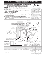
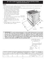
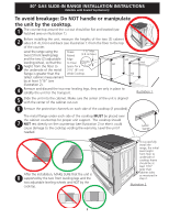
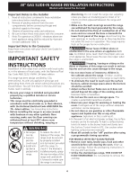
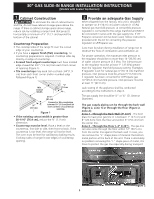
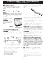
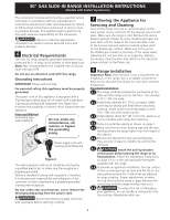
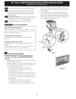
30" GAS SLIDE-IN RANGE INSTALLATION INSTRUCTIONS (Models with Sealed Top Burners) 1 Cabinet Construction To eliminate the risk of cabinet burns and fire, do not have cabinet storage space above the range. If there is cabinet storage space above range, reduce risk by installing a range hood that projects horizontally a minimum of 5" (12.7 cm) beyond the bottom of the cabinet. Countertop Preparation • The cooktop sides of the range fit over the cutout edge of your countertop. • If you have a square finish (flat) countertop, no countertop preparation is required. Cooktop sides lay directly on edge of countertop. • Formed front-edged countertops must have molded edge shaved flat 3/4" (1.9 cm) from each front corner of opening (Figure 1). • Tile countertops may need trim cut back 3/4"(1.9 cm) from each front corner and/or rounded edge flattened (Figure 1). Min. Cutout Width ¾" (1.9 cm) ¾" (1.9 cm) 31½" (81 cm) Formed or tile countertop trimmed ¾" (1.9 cm) back at front corners of countertop opening. Figure 1 • If the existing cutout width is greater than 30-1/16" (76,4 cm), reduce the ¾" (1.9 cm) dimension. • Countertop must be level. Place a level on the countertop, first side to side, then front to back. If the countertop is not level, the range will not be level. The oven must be level for satisfactory baking results. Cooktop sides of range fit over edges of countertop opening. 2 Provide an adequate Gas Supply When shipped from the factory, this unit is designed to operate on 4"(10,16 cm) water column (1.0 kPa) Natural gas manifold pressure. A convertible pressure regulator is connected to the range manifold and MUST be connected in series with the gas supply line. If LP/ Propane conversion kit has been used, follow instructions provided with the kit for converting the pressure regulator to LP/Propane use. Care must be taken during installation of range not to obstruct the flow of combustion and ventilation air. For proper operation, the maximum inlet pressure to the regulator should be no more than 14"(35,56 cm) of water column pressure (3.5 kPa). The inlet pressure to the regulator must be at least 1" (.25 kPa) greater than the regulator manifold pressure setting. Examples: If regulator is set for natural gas 4"(10,16 cm) manifold pressure, inlet pressure must be at least 5"(12.60 cm); if regulator has been converted for LP/Propane gas 10"(25,4 cm) manifold pressure, inlet pressure must be at least 11"(27,9 cm). Leak testing of the appliance shall be conducted according to the instructions in step 4. The gas supply line should be ½" or ¾" I.D. (Interior Diameter) The gas supply piping can be through the back wall (Figure 2, zone 1) or through the floor (Figure 2, zone 2): Zone 1 - Through the Back Wall (7" X 6") - The best place to have your gas line in is between 1" (2.5 cm) and 8" (20.3cm) from the floor and within 3" (7.6 cm) from the center line. Zone 2 - Through the Floor (~2" X 24") - The gas line can also come through the floor within 12" (30.5 cm) from the center line against the back wall. In case, you can remove the "L" shape piece of metal at the bottom metal portion at the back of the unit. There is absolutely no problem removing this "L" shape piece of metal, it is there to protect the gas line especially during transport. Figure 2 5
-
 1
1 -
 2
2 -
 3
3 -
 4
4 -
 5
5 -
 6
6 -
 7
7 -
 8
8 -
 9
9 -
 10
10 -
 11
11 -
12
-
13
-
14
-
15
-
16
-
17
-
18
-
19
-
20
-
21
-
22
-
23
-
24
-
25
-
26
-
27
-
28
-
29
-
30
-
31
-
32
-
33
-
34
-
35
-
36
-
37
-
38
-
39
-
40
 |
 |