Electrolux EW30GS80RS Installation Instructions English Spanish French - Page 4
Gas Slide-in Range Installation Instructions
 |
View all Electrolux EW30GS80RS manuals
Add to My Manuals
Save this manual to your list of manuals |
Page 4 highlights
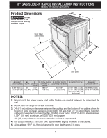
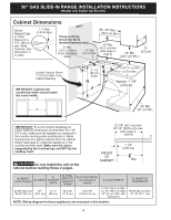
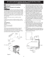
30" GAS SLIDE-IN RANGE INSTALLATION INSTRUCTIONS (Models with Sealed Top Burners) Cabinet Dimensions Shave Raised Edge 1 ½" Max. (3,8 cm Max.) WALL to Clear These surfaces Space for a should be flat & 311/2" (80 cm) leveled (hatched area). min. Wide Cooktop. See Dimension C in table. 5" Min. (12,7 cm Min.) From Wall Both Sides 30" Min. (76,2 cm) Min. (See page 3, note 3) Locate Cabinet Doors 1" (2,5 cm) Min. from Cutout Opening. IMPORTANT: Cabinet and countertop width should match the cutout width. E E *IMPORTANT: To avoid cooktop breakage for cutout width (E dimension) of more than 30 1/16" (76,4 cm), make sure the appliance is centered in the counter opening while pushing into it. Raise leveling legs at a higher position than the cabinet height (see page 5), insert the appliance in the counter and then level. Make sure the unit is supported by the leveling legs and NOT by the cooktop itself. Do not install the unit in the cabinet before reading these 2 pages. 22 7/8" (58,1 cm) min. 23 1/4" (59,05 cm) max. (See page 3, note 4) FRONT OF CABINET 1 1/8" (2,86 cm) F Ref. A. HEIGHT (Under Cooktop) B. WIDTH C. COOKTOP WIDTH D. TOTAL DEPTH TO FRONT OF RANGE 35 5/8" (90,5 cm) 30" 31 ½" 28 5/16" 36 5/8" (93 cm) (76,2 cm) (80 cm) (71,9 cm) E. CUTOUT WIDTH* (Countertop and cabinet) 30±1/16" (76,2±0,15 cm) F. CUTOUT DEPTH G. HEIGHT OF COUNTERTOP 21 3/4" (55,2 cm) Min. 22 1/8" (56,2 cm) Max 24" (61 cm) Min. with backguard 36 5/8" (93 cm) Max. 35 7/8" (91,1 cm) NOTE: Wiring diagram for these appliances are enclosed in this booklet. 4
-
 1
1 -
 2
2 -
 3
3 -
 4
4 -
 5
5 -
 6
6 -
 7
7 -
 8
8 -
 9
9 -
 10
10 -
11
-
12
-
13
-
14
-
15
-
16
-
17
-
18
-
19
-
20
-
21
-
22
-
23
-
24
-
25
-
26
-
27
-
28
-
29
-
30
-
31
-
32
-
33
-
34
-
35
-
36
-
37
-
38
-
39
-
40
-
41
-
42
-
43
-
44
-
45
-
46
-
47
-
48
 |
 |
