Epson C31C636A898 Technical Reference - Page 23
Power Switch Cover, Connector Cover
 |
View all Epson C31C636A898 manuals
Add to My Manuals
Save this manual to your list of manuals |
Page 23 highlights
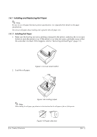
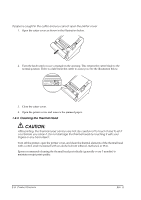
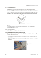
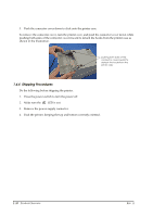
TM-T88IV Technical Reference Guide 1.4.4 Power Switch Cover Install the power switch cover that comes with the TM-T88IV onto the printer to prevent inadvertent changing of the power switch, to prevent tampering, and to improve the appearance of the printer. To reset the TM printer when the power switch cover is installed, insert a long, thin object (such as the end of a paper clip) into the hole in the power switch cover and press the power switch. Power Switch Cover Note: If an accident occurs with the power switch cover attached, unplug the power cord immediately. Continued use may cause fire or shock. 1.4.5 Connector Cover Use the following method to attach the connector cover. 1.4.5.1 Attaching and Removing the Connector Cover These instructions apply if a connector cover is packed with your printer to protect your cables. To attach it, follow the steps below: 1. First, connect all the cables. The connector cover has three possible cable exits: on the right, left, and back. 2. Position the two hooks on the connector cover so that they hook the printer case, as shown in illustration. The two hooks Rev. A Product Overview 1-9
-
 1
1 -
2
-
3
-
4
-
5
-
6
-
7
-
8
-
9
-
10
-
11
-
12
-
13
-
14
-
15
-
16
-
17
-
 18
18 -
 19
19 -
 20
20 -
 21
21 -
 22
22 -
 23
23 -
 24
24 -
 25
25 -
 26
26 -
 27
27 -
 28
28 -
29
-
30
-
31
-
32
-
33
-
34
-
35
-
36
-
37
-
38
-
39
-
40
-
41
-
42
-
43
-
44
-
45
-
46
-
47
-
48
-
49
-
50
-
51
-
52
-
53
-
54
-
55
-
56
-
57
-
58
-
59
-
60
-
61
-
62
-
63
-
64
-
65
-
66
-
67
-
68
-
69
-
70
-
71
-
72
-
73
-
74
-
75
-
76
-
77
-
78
-
79
-
80
-
81
-
82
-
83
-
84
-
85
-
86
-
87
-
88
-
89
-
90
 |
 |
