Epson C31C636A898 Technical Reference - Page 29
Rev. A, Setup, TM-T88IV Technical Reference Guide, Factory setting
 |
View all Epson C31C636A898 manuals
Add to My Manuals
Save this manual to your list of manuals |
Page 29 highlights
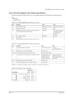
TM-T88IV Technical Reference Guide 2.2.2.2 DIP switch settings for other interface specifications The following DIP switch functions are for parallel interface/USB/Ethernet model printers. Note: * Factory setting Table 2-6 Parallel/USB/Ethernet DIP switch bank 1 SW Function 1-1 Automatic line feed 1-2 Receive buffer size 1-3 Select paper sensors to output paper-end signals. (Command default setting value.) 1-4 1-5 ~ 1-8 Error signal output Not defined (Always use printer with these switches set to OFF.) ON Enabled at all times 45 bytes Disabled Disabled - OFF Disabled at all times * 4KB * Roll Paper end sensor enabled, Roll Paper nearend sensor enabled Enabled - * Table 2-7 Parallel/USB/Ethernet DIP switch bank 2 SW Function 2-1 Handshake (BUSY conditions) 2-2 Reserved (do not change setting) 2-3, 2-4 Print density selection/low-power mode 2-5 Conditions for canceling receive buffer BUSY state 2-6, 2-7 Reserved (do not change setting) 2-8 Pin #31reset signal (do not change setting) ON OFF • Receive buffer full • Offline * • Receive buffer full Fixed to OFF (See separate table.) Releases BUSY when remaining receive buffer capacity reaches 138 bytes. Releases BUSY when remaining receive buffer capacity reaches 256 bytes. Fixed to OFF Fixed to ON DIP SW2-1: For details on the BUSY condition, also refer to "Busy State" (page 3-11). Table 2-8 Selection of print density Switch no. Print density 2-3 2-4 Print density Low-power mode ON ON Normal* OFF OFF Medium ON OFF Print density Dark OFF ON Rev. A Setup 2-5
-
 1
1 -
2
-
3
-
4
-
5
-
6
-
7
-
8
-
9
-
10
-
11
-
12
-
13
-
14
-
15
-
16
-
17
-
18
-
19
-
20
-
21
-
22
-
23
-
 24
24 -
 25
25 -
 26
26 -
 27
27 -
 28
28 -
 29
29 -
 30
30 -
 31
31 -
 32
32 -
 33
33 -
 34
34 -
35
-
36
-
37
-
38
-
39
-
40
-
41
-
42
-
43
-
44
-
45
-
46
-
47
-
48
-
49
-
50
-
51
-
52
-
53
-
54
-
55
-
56
-
57
-
58
-
59
-
60
-
61
-
62
-
63
-
64
-
65
-
66
-
67
-
68
-
69
-
70
-
71
-
72
-
73
-
74
-
75
-
76
-
77
-
78
-
79
-
80
-
81
-
82
-
83
-
84
-
85
-
86
-
87
-
88
-
89
-
90
 |
 |
