Epson EPL-N1200 Service Manual - Page 72
Controller Board, C205 MAIN, Forced Laser Diode
 |
View all Epson EPL-N1200 manuals
Add to My Manuals
Save this manual to your list of manuals |
Page 72 highlights
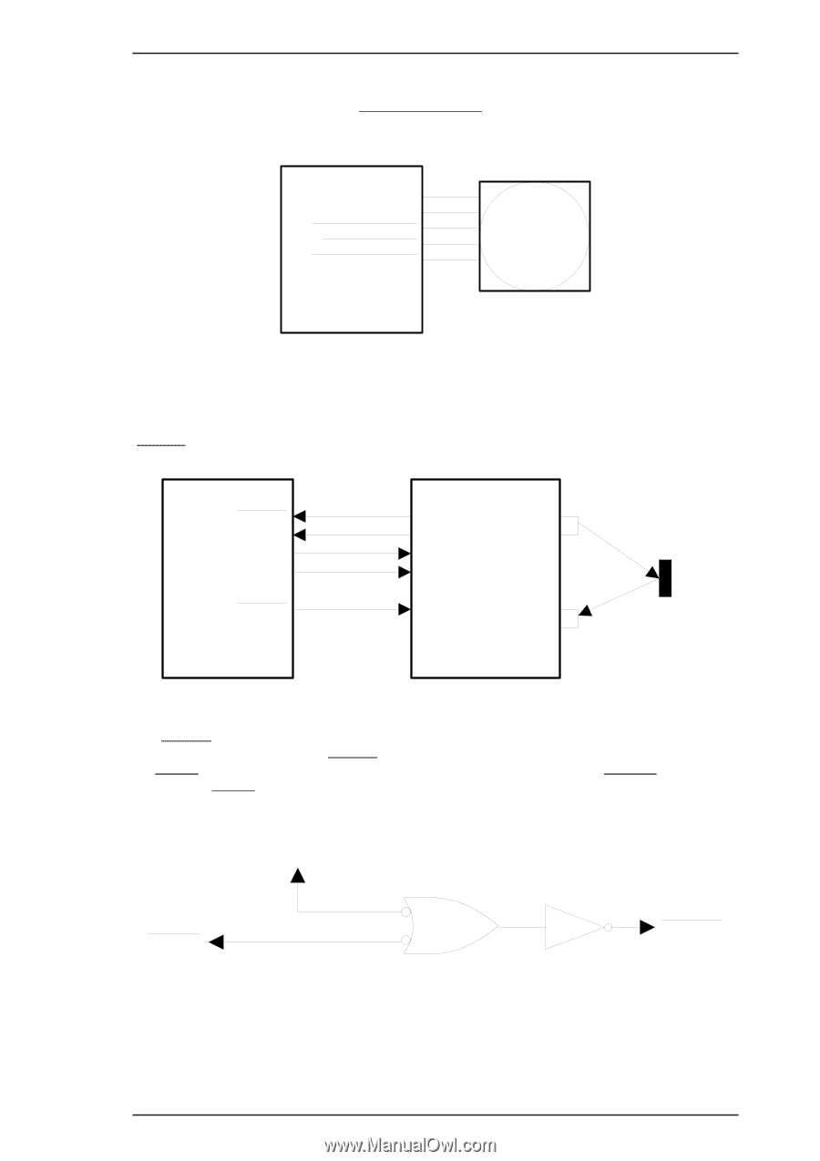
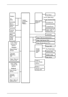
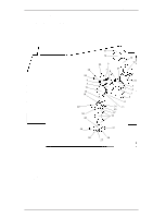
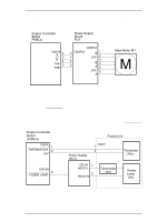
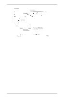
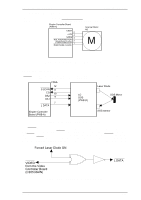
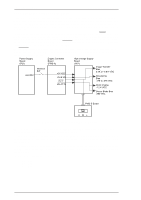
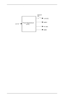
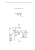
EPL-N1200 Service Manual Operating Principles 2.1.2.3 Scanner Mirror Motor Control Figure 2-18 is the scanner mirror motor (M2) control circuit. The scanner mirror motor is driven while the scanner motor receives the POLYGON MOTOR (M2:ON) signal. Engine Controller Board (PWB-A) CN5A 5 +24V 4 GND2 3 POLYGON MOTOR 2 PORYGON LOCK 1 PORYGON CLOCK Scanner Motor M2 M Figure 2-18. Scanner Motor Control Circuit 2.1.2.4 Laser Diode Drive Figure 2-19 shows the laser diode drive circuit. Laser diode emission is controlled by three signals (L DATA, DA1, and DA2) from the engine controller board (PWB-A). CN5A 12 S SCAN 11 CO 10 DA2 9 DA1 7 L DATA LD SOS (PWB-D) Laser Diode SOS Mirror Engine Controller Board (PWB-A) SOS sensor Figure 2-19. Laser Diode Drive Circuit The L DATA signal is the laser ON/OFF signal. When it is LOW, the laser emits, and when it is HIGH, the laser stops emitting. L DATA is the combination of the two signals in the figure below. If the VIDEO or the FORCED LASER DIODE ON signal is activated (LOW), the L DATA signal will be active. The VIDEO signal is an image signal sent from the video controller board (C205 MAIN board). The FORCED LASER DIODE ON signal is a laser emission signal to apply the laser beam to the SOS sensor. Forced Laser Diode ON VIDEO from the Video Controller Board (C205 MAIN) Figure 2-20. /L DATA Generation Circuit L DATA Rev. A 2-13
-
 1
1 -
2
-
3
-
4
-
5
-
6
-
7
-
8
-
9
-
10
-
11
-
12
-
13
-
14
-
15
-
16
-
17
-
18
-
19
-
20
-
21
-
22
-
23
-
24
-
25
-
26
-
27
-
28
-
29
-
30
-
31
-
32
-
33
-
34
-
35
-
36
-
37
-
38
-
39
-
40
-
41
-
42
-
43
-
44
-
45
-
46
-
47
-
48
-
49
-
50
-
51
-
52
-
53
-
54
-
55
-
56
-
57
-
58
-
59
-
60
-
61
-
62
-
63
-
64
-
65
-
66
-
 67
67 -
 68
68 -
 69
69 -
 70
70 -
 71
71 -
 72
72 -
 73
73 -
 74
74 -
 75
75 -
 76
76 -
 77
77 -
78
-
79
-
80
-
81
-
82
-
83
-
84
-
85
-
86
-
87
-
88
-
89
-
90
-
91
-
92
-
93
-
94
-
95
-
96
-
97
-
98
-
99
-
100
-
101
-
102
-
103
-
104
-
105
-
106
-
107
-
108
-
109
-
110
-
111
-
112
-
113
-
114
-
115
-
116
-
117
-
118
-
119
-
120
-
121
-
122
-
123
-
124
-
125
-
126
-
127
-
128
-
129
-
130
-
131
-
132
-
133
-
134
-
135
-
136
-
137
-
138
-
139
-
140
-
141
-
142
-
143
-
144
-
145
-
146
-
147
-
148
-
149
 |
 |