Epson EPL-N1200 Service Manual - Page 73
High-Voltage Supply Block Diagram
 |
View all Epson EPL-N1200 manuals
Add to My Manuals
Save this manual to your list of manuals |
Page 73 highlights
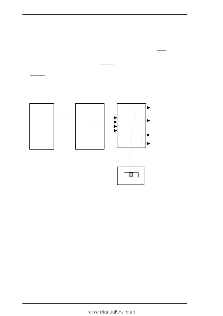
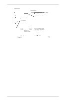
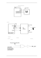
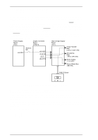
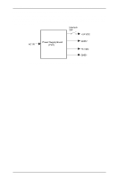
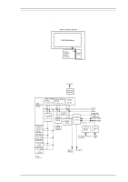
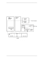
Operating Principles EPL-N1200 Service Manual 2.1.2.5 Bias Voltages and Laser Drive Timing Figure 2-21 is a diagram of the drum charge bias voltage, image transfer bias voltage, doctor blade bias voltage, and the developing bias voltage control circuit. These bias voltages are generated from the +24 VDC from the high-voltage supply board (HV1). If the printer detects the top cover open condition, the interlock switch is set to OFF, which cuts the +24 VDC, which, in turn, cuts the bias voltages. These bias voltages are controlled by the engine controller board (PWB-A). The HV-T signal is the image transfer (roller) bias voltage control. While this signal is LOW, the image transfer roller is charged to 3.2K VDC by the high-voltage supply circuit. And while this signal is HIGH, the image transfer roller is charged to -0.8K VDC. The HV-CT.R signal controls the drum charge. While this signal is LOW, the PC drum is charged to -1.2K VDC. The HV-B.VR signal is an analog signal for developing bias voltage control. This signal controls the bias voltage level (-175 V to -375 VDC) using analog data. The image density is controlled by the developing bias voltage level. Power Suppry Board (PU1) Engine Controller Board (PWB-A) +24 VDC Interlock SW +24 VDC HV-B.VR HV-T HV-CT.R High Voltage Supply Board (HV1) Image Transfer Bias 3.2K or -0.8 K VDC Developing Bias -175 to -375 VDC Drum Charge -1.2 K VDC Doctor Blade Bias -550 VDC PWB-S Board HML Figure 2-21. High-Voltage Supply Block Diagram There is a three position slide switch on the PWB-S board. The switch can select one of three image transfer bias current values. The standard position is M. If the printer is used in an environment with high temperature and high humidity and an image transfer problem occurs, especially with small size of paper, it is recommended that the switch be positioned at H. If the printer is used in an environment with low temperature and low humidity and a toner smear problem occurs at the age of the transparency sheets, it is recommended that the switch be positioned at L Each position's current value is shown below. H: 18 uA M: 8 uA L: 5 uA 2-14 Rev. A
-
 1
1 -
2
-
3
-
4
-
5
-
6
-
7
-
8
-
9
-
10
-
11
-
12
-
13
-
14
-
15
-
16
-
17
-
18
-
19
-
20
-
21
-
22
-
23
-
24
-
25
-
26
-
27
-
28
-
29
-
30
-
31
-
32
-
33
-
34
-
35
-
36
-
37
-
38
-
39
-
40
-
41
-
42
-
43
-
44
-
45
-
46
-
47
-
48
-
49
-
50
-
51
-
52
-
53
-
54
-
55
-
56
-
57
-
58
-
59
-
60
-
61
-
62
-
63
-
64
-
65
-
66
-
67
-
 68
68 -
 69
69 -
 70
70 -
 71
71 -
 72
72 -
 73
73 -
 74
74 -
 75
75 -
 76
76 -
 77
77 -
 78
78 -
79
-
80
-
81
-
82
-
83
-
84
-
85
-
86
-
87
-
88
-
89
-
90
-
91
-
92
-
93
-
94
-
95
-
96
-
97
-
98
-
99
-
100
-
101
-
102
-
103
-
104
-
105
-
106
-
107
-
108
-
109
-
110
-
111
-
112
-
113
-
114
-
115
-
116
-
117
-
118
-
119
-
120
-
121
-
122
-
123
-
124
-
125
-
126
-
127
-
128
-
129
-
130
-
131
-
132
-
133
-
134
-
135
-
136
-
137
-
138
-
139
-
140
-
141
-
142
-
143
-
144
-
145
-
146
-
147
-
148
-
149
 |
 |