Epson LX-86 User Manual - Page 7

s, List - ribbon

Page 7 highlights

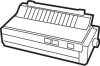
List of Figures l-l Printer parts 3 l-2 Paper feed knob installation 5 l-3 Ribbon cassette l-4 Print head assembly 6 l-5 Ribbon cassette installation 7 l-6 Ribbon placement 8 l-7 IX-86 ready for paper loading 9 l-8 Control panel 10 l-9 Test patterns 12 l-10 Cable connection 13 2-l Turning SelecType on 16 3-l A capital T 21 3-2 The three pitches of the LX-86 23 3-3 IX-86 dot matrix characters 24 6-l Emphasized and standard print 39 6-2 Double-strike and standard print 41 6-3 Double-width and standard characters 42 6-4 Italic and pica 44 6-5 The underline mode 45 6-6 Special graphics characters 51 7-1 Standard line spacing 56 8-l Grid for designing draft characters 60 8-2 Correct and incorrect designs 61 8-3 Design for character 62 8-4 Using the bottom eight rows 63 8-5 Grid for NLQ characters 66 8-6 Data numbers for one column 67 8-7 Arrow design and data numbers 68 9-l Pin labels 75 9-2 Calculating numbers for pin patterns 75 9-3 Designing in different densities 81 9-4 Arrow design 82 9-5 First line of arrow figure 82 9-6 Result of incorrect program 84 9-7 Pin patterns of incorrect program 85 D-l DIP switch location D-l vii

  • 1
  • 2
  • 3
  • 4
  • 5
  • 6
  • 7
  • 8
  • 9
  • 10
  • 11
  • 12
  • 13
  • 14
  • 15
  • 16
  • 17
  • 18
  • 19
  • 20
  • 21
  • 22
  • 23
  • 24
  • 25
  • 26
  • 27
  • 28
  • 29
  • 30
  • 31
  • 32
  • 33
  • 34
  • 35
  • 36
  • 37
  • 38
  • 39
  • 40
  • 41
  • 42
  • 43
  • 44
  • 45
  • 46
  • 47
  • 48
  • 49
  • 50
  • 51
  • 52
  • 53
  • 54
  • 55
  • 56
  • 57
  • 58
  • 59
  • 60
  • 61
  • 62
  • 63
  • 64
  • 65
  • 66
  • 67
  • 68
  • 69
  • 70
  • 71
  • 72
  • 73
  • 74
  • 75
  • 76
  • 77
  • 78
  • 79
  • 80
  • 81
  • 82
  • 83
  • 84
  • 85
  • 86
  • 87
  • 88
  • 89
  • 90
  • 91
  • 92
  • 93
  • 94
  • 95
  • 96
  • 97
  • 98
  • 99
  • 100
  • 101
  • 102
  • 103
  • 104
  • 105
  • 106
  • 107
  • 108
  • 109
  • 110
  • 111
  • 112
  • 113
  • 114
  • 115
  • 116
  • 117
  • 118
  • 119
  • 120
  • 121
  • 122
  • 123
  • 124
  • 125
  • 126
  • 127
  • 128
  • 129
  • 130
  • 131
  • 132
  • 133
  • 134
  • 135
  • 136
  • 137
  • 138
  • 139
  • 140
  • 141
  • 142
  • 143
  • 144
  • 145
  • 146

List
of
Figures
l-l
Printer parts
................................
l-2
Paper feed knob installation
...................
l-3
Ribbon cassette.
.............................
l-4
Print head assembly
..........................
l-5
Ribbon cassette installation
....................
l-6
Ribbon placement
...........................
l-7
IX-86 ready for paper loading
..................
l-8
Control panel
...............................
l-9
Test patterns
................................
l-10 Cable connection
............................
2-l
Turning SelecType on . . . . . . . . . . . . . . . . . . . . . . . . .
16
3-l
A capital T
.................................
21
3-2
The three pitches of the LX-86
.................
23
3-3
IX-86 dot matrix characters
....................
24
6-l
Emphasized and standard print.
........
.......
6-2
Double-strike and standard print.
.......
.......
6-3
Double-width and standard characters
...
.......
6-4
Italic and pica.
......................
.......
6-5
The underline mode
.................
.......
6-6
Special graphics characters
.............
.......
7-1
Standard line spacing. . . . . . . . . . . . . . . . . . . . . . . . .
56
8-l
Grid for designing draft characters
..............
60
8-2
Correct and incorrect designs
...................
61
8-3
Design for character
..........................
62
8-4
Using the bottom eight rows
...................
63
8-5
Grid for NLQ characters
.......................
66
8-6
Data numbers for one column
..................
67
8-7
Arrow design and data numbers
................
68
9-l
Pin labels
..................................
9-2
Calculating numbers for pin patterns
............
9-3
Designing in different densities
.................
9-4
Arrow design
...............................
9-5
First line of arrow figure
.......................
9-6
Result of incorrect program
....................
9-7
Pin patterns of incorrect program
...............
D-l DIP switch location
..........................
3
5
6
7
8
9
10
12
13
39
41
42
44
45
51
75
75
81
82
82
84
85
D-l
vii