Frigidaire FFEH3054US Installation Instructions - Page 5
A. Power Cord Connections, To Fig.12, 5b. Power Cord Connections, To Fig. 13. - reviews
 |
View all Frigidaire FFEH3054US manuals
Add to My Manuals
Save this manual to your list of manuals |
Page 5 highlights
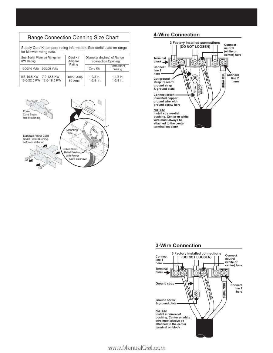
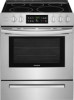
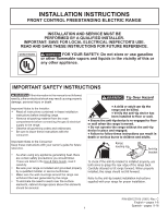
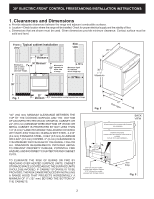
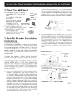
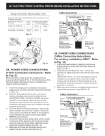
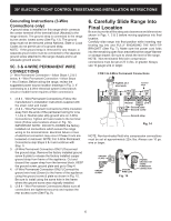
30" ELECTRIC FRONT CONTROL FREESTANDING INSTALLATION INSTRUCTIONS Fig. 10 NOTE: Internal white wire not present on all models. Fig. 12 5B. POWER CORD CONNECTIONS (3-Wire Connection Instructions For existing installations ONLY - Refer Fig. 11 to Fig. 13). 1. Follow the manufacturer's installation instructions supplied with the strain relief and install (Also see 5A. POWER CORD CONNECTIONS (4-Wire Connection Instructions - Refer to Fig.12) Before wiring the range review the suggested power source location drawing in Fig. 3. If connecting to a 4-Wire electrical system (new branch-circuit or mobile home requires 4-Wire connection): Figs. 9, 10 & 11). 2. Insert the end connectors for Line 1, Line 2 and Neutral and tighten securely to the terminal block (See Fig. 13). IMPORTANT NOTE: DO NOT LOOSEN the factory installed nut connections which secure the range wiring to the terminal block. Electrical failure or loss of electrical connection may occur if these 3 nuts are loosened or removed. 1. Follow the manufacturer's installation instructions supplied with the strain relief and install (Also see Figs. 3. Make sure all connections are tightened securely and replace the rear access cover (See Fig. 9). 9, 10 & 11). 2. Insert the end connectors for Line 1, Line 2 and Neutral and tighten securely to the terminal block. IMPORTANT NOTE: DO NOT LOOSEN the factory installed nut connections which secure the range wiring to the terminal block. Electrical failure or loss of electrical connection may occur if these 3 nuts are loosened or removed. 3. You must disconnect the ground strap. Remove the factory installed ground screw & plate to release the copper ground strap from the frame of the appliance. Cut and discard the copper ground strap & plate. KEEP the ground screw. 4. Connect the ground wire (Green) lead with the eyelet to the frame of the appliance with the ground screw using the same hole in the frame where the ground screw was originally installed (See Fig. 12). 5. Make sure all screws are tightened securely and replace the rear access cover (See Fig. 9). 5 NOTE: Internal white wire not present on all models. Fig. 13
-
 1
1 -
 2
2 -
 3
3 -
 4
4 -
 5
5 -
 6
6 -
 7
7 -
 8
8 -
 9
9 -
 10
10 -
 11
11 -
12
-
13
-
14
-
15
-
16
 |
 |