Frigidaire FPGH3077RF Installation Instructions - Page 4
Tools you will need, Normal Installation Steps - gas range
 |
View all Frigidaire FPGH3077RF manuals
Add to My Manuals
Save this manual to your list of manuals |
Page 4 highlights
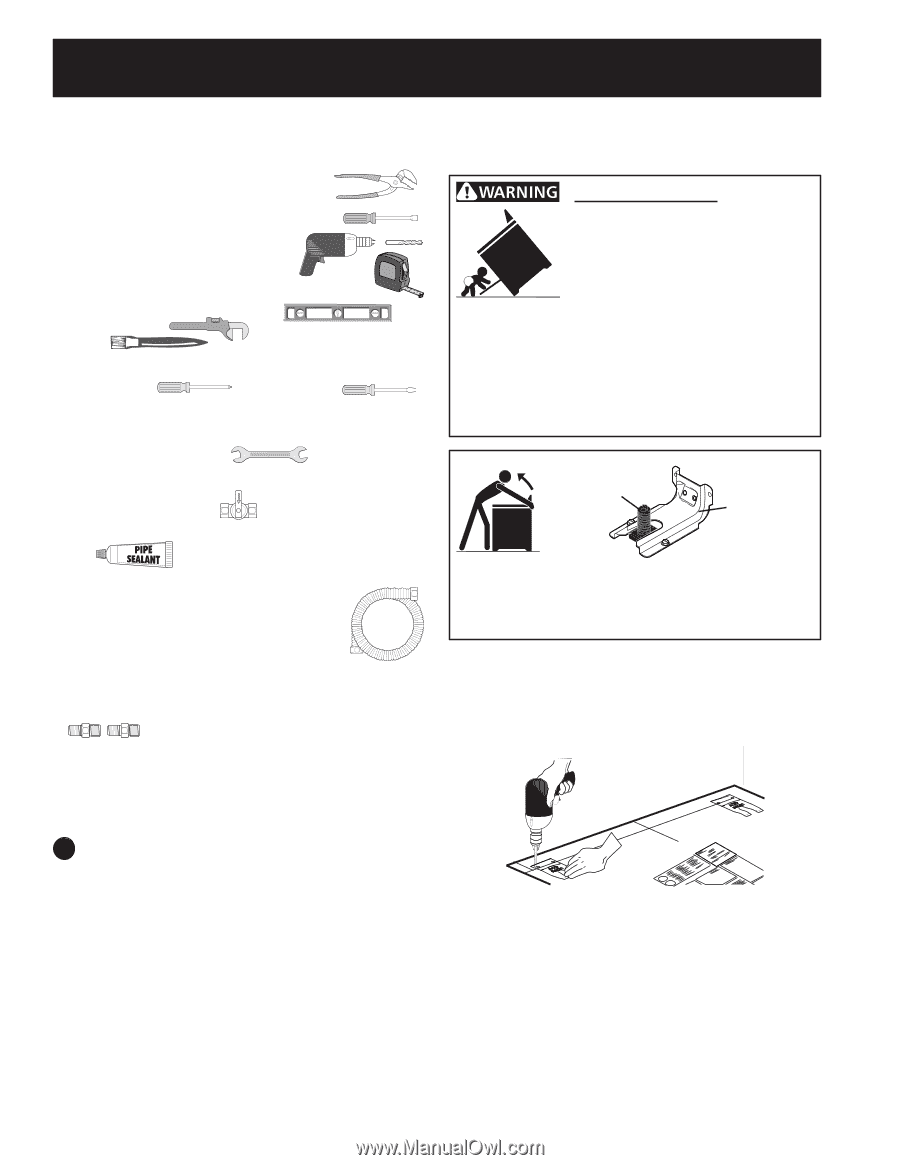
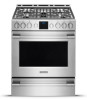
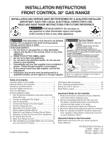
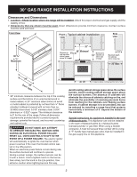
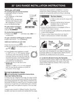
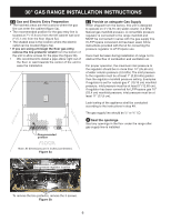
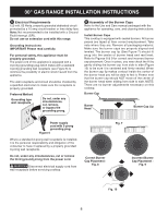
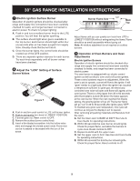
30" GAS RANGE INSTALLATION INSTRUCTIONS Tools you will need For leveling legs and anti-tip brackets: ● Adjustable wrench or channel lock pliers ● 5/16" Nutdriver or Flat Head Screw Driver ● Electric Drill & 1/8 Diameter Drill Bit (5/32" Masonry Drill Bit if installing in concrete) ● Level & Measuring Tape For gas supply connection: ● Pipe Wrench ● Brush For burner flame adjustment ● Phillips head and blade-type screwdrivers For gas conversion (LP/Propane or Natural): ● Open end wrench - 1/2" Additional materials you will need ● Gas line shut-off valve ● Pipe joint sealant that resists action of LP/ Propane gas ● A new flexible metal appliance conduit (½" NPT x ¾" or ½" I.D.) must be design certified by CSA International. Because solid pipe restricts moving the range we recommend using a new flexible conduit (4 feet length) for each new installation and additional reinstallations. ● Always use the (2) new flare union adapters ½" NPT x ¾" or ½" I.D.) supplied with the new flexible appliance conduit for connection of the range. Instructions are provided for installation in wood or cement floor. When fastening to floor, be sure that screws do not penetrate electrical wiring or plumbing. Tip Over Hazard • A child or adult can tip the range and be killed. • Verify the anti-tip device has been installed to floor or wall as per installation instructions. • Ensure the anti-tip device is re-engaged to floor or wall when the range is moved. • Do not operate the range without the anti-tip device in place and engaged. • Failure to follow these instructions can result in death or serious burns to children and adults. Range Leveling Leg Anti-Tip Bracket To check if the anti-tip bracket is installed properly, use both arms and grasp the rear edge of range back. Carefully attempt to tilt range forward. When properly installed, the range should not tilt forward. A. Locate the Bracket Using the Template Locate the bracket position (right or left side) by placing the template symmetrically to the center of the final range position. Mark the location of the screw holes, shown on template. Normal Installation Steps 1 Anti-tip Bracket Installation Instructions Important Safety Warning To reduce the risk of tipping of the range, the range must be secured to the floor by the properly installed anti-tip bracket and screws packed with the range. Failure to install the antitip bracket will allow the range to tip over if excessive weight is placed on an open door or if child climbs upon it. Serious injury might result from spilled hot liquids or from the range itself. If range is ever moved to a different location, the anti-tip brackets must also be moved and installed with the range. Figure 1 4
-
 1
1 -
 2
2 -
 3
3 -
 4
4 -
 5
5 -
 6
6 -
 7
7 -
 8
8 -
 9
9 -
 10
10 -
11
-
12
-
13
-
14
-
15
-
16
-
17
-
18
-
19
-
20
-
21
-
22
-
23
-
24
-
25
-
26
-
27
-
28
-
29
-
30
-
31
-
32
 |
 |