Frigidaire FPGH3077RF Installation Instructions - Page 8
Electrical Requirements, Assembly of the Burner Caps
 |
View all Frigidaire FPGH3077RF manuals
Add to My Manuals
Save this manual to your list of manuals |
Page 8 highlights
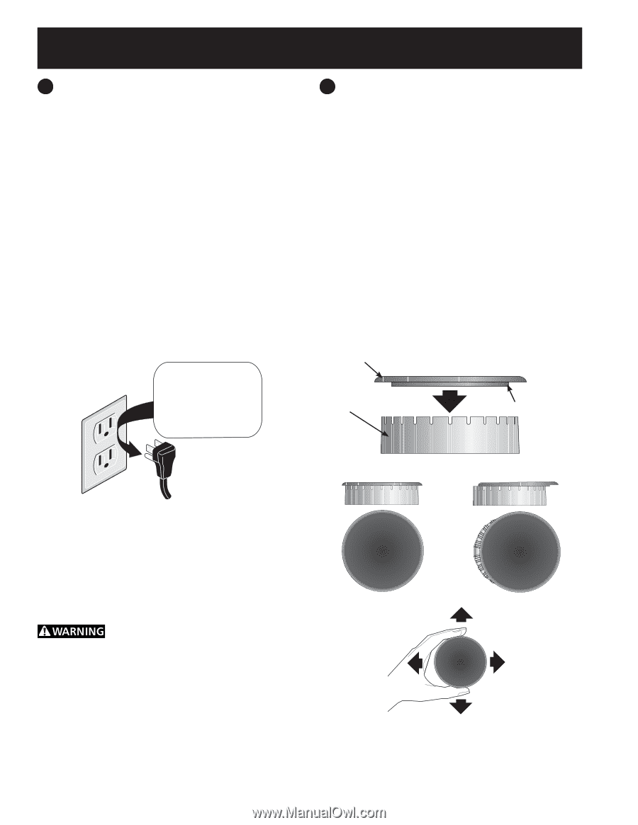
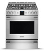
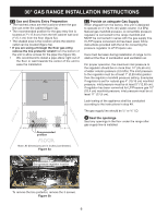
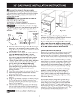
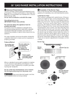
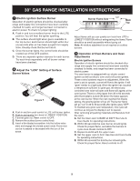
30" GAS RANGE INSTALLATION INSTRUCTIONS 5 Electrical Requirements 120 volt, 60 Hertz, properly grounded dedicated circuit protected by a 15 amp circuit breaker or time delay fuse. Note: Not recommended to be installed with a Ground Fault Interrupt (GFI). Do not use an extension cord with this range. Grounding Instructions IMPORTANT Please read carefully. For personal safety, this appliance must be properly grounded. The power cord of this appliance is equipped with a 3-prong (grounding) plug which mates with a standard 3-prong grounding wall receptacle (see Figure 6) to minimize the possibility of electric shock hazard from the appliance. The wall receptacle and circuit should be checked by a qualified electrician to make sure the receptacle is properly grounded. Preferred Method Grounding type wall receptacle Do not, under any circumstances, cut, remove, or bypass the grounding prong. 6 Assembly of the Burner Caps Refer to the Use and Care manual packaged with the appliance for operating, care, and cleaning instructions. Install Burner Caps This cooktop is equipped with sealed burners. All burner pieces are taped at their correct emplacement. Take note where they are. Remove all packaging material. Make sure the burner caps are properly aligned and leveled. The burner cap lip (See Figure 7) should fit snug into the center of burner head and rest level. Refer to Figures 8 & 9 for correct and incorrect burner cap placement. Once in place, you may check the fit by gently sliding the burner cap from side to side (Figure 10) to be sure it is centered and firmly seated. When the burner cap lip makes contact inside the center of the burner head you will be able to feel it. Please note that the burner cap should NOT move off the center of the burner head when sliding from side to side. NOTE: There are no burner adjustments necessary on this cooktop. Burner Cap Burner Head Burner Cap Lip Power supply cord with 3-prong grounding plug. Figure 6 Where a standard 2-prong wall receptacle is installed, it is the personal responsibility and obligation of the consumer to have it replaced by a properly grounded 3-prong wall receptacle. Do not, under any circumstances, cut or remove the third (ground) prong from the power cord. Disconnect electrical supply cord from wall receptacle before servicing cooktop. Correct Burner Cap Placement - Fig. 8 Fig. 7 Incorrect Burner Cap Placement - Fig. 9 Fig. 10 8
-
 1
1 -
2
-
 3
3 -
 4
4 -
 5
5 -
 6
6 -
 7
7 -
 8
8 -
 9
9 -
 10
10 -
 11
11 -
 12
12 -
 13
13 -
14
-
15
-
16
-
17
-
18
-
19
-
20
-
21
-
22
-
23
-
24
-
25
-
26
-
27
-
28
-
29
-
30
-
31
-
32
 |
 |