Frigidaire FPGH3077RF Installation Instructions - Page 6
Provide an adequate Gas Supply, Seal the openings, Gas and Electric Entry Preparation - dimensions
 |
View all Frigidaire FPGH3077RF manuals
Add to My Manuals
Save this manual to your list of manuals |
Page 6 highlights
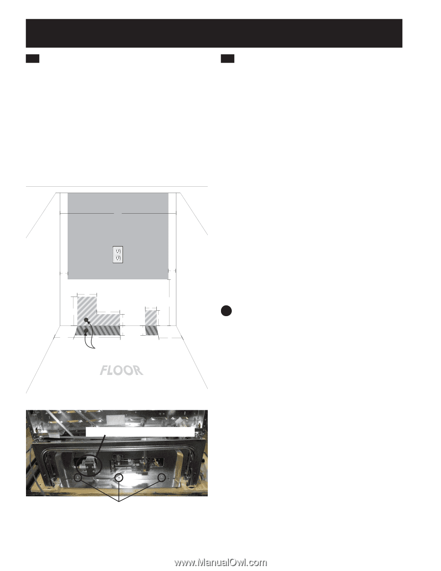
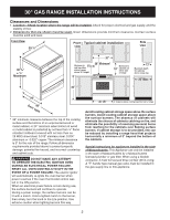
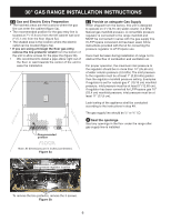
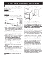
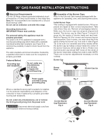
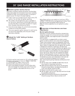
30" GAS RANGE INSTALLATION INSTRUCTIONS 2.1 Gas and Electric Entry Preparation • The hatched areas are the locations where the gas line can enter the cabinet (figure 5a). • The recommended position for the gas entry line is located at 7" (17,8 cm) from the left cabinet wall and 2" (5,1 cm) from the floor (figure 5a). • The shaded area is the location where the electric outlet can be located (figure 5a). • If you are using a through the floor gas entry, remove the line protector shield from the bottom of the unit to allow access for the pipe line (figure 5b). • We recommend to install a pipe elbow right out of the floor or wall towards the center of the unit to ease the installation. 30 (76.2) 2.2 Provide an adequate Gas Supply When shipped from the factory, this unit is designed to operate on 4" (10,16 cm) water column (1,0 kPa) Natural gas manifold pressure. A convertible pressure regulator is connected to the range manifold and MUST be connected in series with the gas supply line. If LP/Propane conversion kit has been used, follow instructions provided with the kit for converting the pressure regulator to LP/Propane use. Care must be taken during installation of range not to obstruct the flow of combustion and ventilation air. For proper operation, the maximum inlet pressure to the regulator should be no more than 14" (35,56 cm) of water column pressure (3,5 kPa). The inlet pressure to the regulator must be at least 1" (0,25 kPa) greater than the regulator manifold pressure setting. Examples: If regulator is set for natural gas 4" (10,16 cm) manifold pressure, inlet pressure must be at least 5" (12,60 cm); if regulator has been converted for LP/Propane gas 10" (25,4 cm) manifold pressure, inlet pressure must be at least 11" (27,9 cm). 2 (5.1) 2 (5.1) 7½ 4.5 5 6 3 12 (30.5) 3 4 2½ 2½ 11 5 Recommended position WALL Leak testing of the appliance shall be conducted according to the instructions in step 4H. The gas supply line should be ½" or ¾" I.D. 3 Seal the openings Seal any openings in the floor under the range after gas supply line is installed. Note: All dimensions are in inches (centimeter). Figure 5a Gas pressure regulator location WALL To remove the line protector, remove the 3 screws. Figure 5b 6
-
 1
1 -
 2
2 -
 3
3 -
 4
4 -
 5
5 -
 6
6 -
 7
7 -
 8
8 -
 9
9 -
 10
10 -
 11
11 -
 12
12 -
13
-
14
-
15
-
16
-
17
-
18
-
19
-
20
-
21
-
22
-
23
-
24
-
25
-
26
-
27
-
28
-
29
-
30
-
31
-
32
 |
 |