Fujitsu 4340C Cleaning & Maintenance - Page 21
Spare Pad ASSY. One spare Pad ASSY is provided as the, Sets the SCSI ID. Default ID is 5. - fi flatbed scanner
 |
UPC - 097564304156
View all Fujitsu 4340C manuals
Add to My Manuals
Save this manual to your list of manuals |
Page 21 highlights
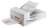
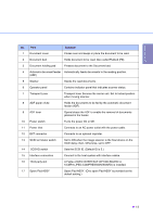
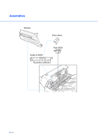
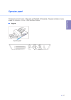
DESCRIPTION No. Part Function 1 Document cover Closes over and keeps in place the document to be read. 2 Document bed Holds document to be read. Also called Flatbed (FB). 3 Document holding pad Presses document to the Document bed. 4 Automatic document feeder Automatically feeds documents to the reading position. (ADF) 5 Stacker Stacks the read documents. 6 Operator panel Contains indicator panel that indicates scanner status. 7 Transport Lever Transport lever Secures the carrier unit. Set to locked position when moving scanner. 8 ADF paper chute Holds the documents to be fed by the automatic document feeder (ADF). 9 ADF lever Opens/closes the ADF to enable the removal of documents jammed in the feeder. 10 Power switch Turns the power On or Off. 11 Power inlet Connects to an AC power outlet with the power cable. 12 EXT connector Connects to an optional imprinter. 13 SCSI terminator switch Set to ON when the image scanner is the final device on the SCSI daisy chain. Otherwise, set to OFF. 14 SCSI-ID switch Sets the SCSI ID. (Default ID is 5.) 15 Interface connectors Connect to the host system with interface cables. 16 Third party slot A Fujitsu VIDEO INTERFACE OPTION BOARD or fi-CMP3 (JPEG COMPRESSION BOARD) is installed. 17 Spare Pad ASSY Spare Pad ASSY. (One spare Pad ASSY is provided as the default setting.) G 1-3
-
 1
1 -
2
-
3
-
4
-
5
-
6
-
7
-
8
-
9
-
10
-
11
-
12
-
13
-
14
-
15
-
 16
16 -
 17
17 -
 18
18 -
 19
19 -
 20
20 -
 21
21 -
 22
22 -
 23
23 -
 24
24 -
 25
25 -
 26
26 -
27
-
28
-
29
-
30
-
31
-
32
-
33
-
34
-
35
-
36
-
37
-
38
-
39
-
40
-
41
-
42
-
43
-
44
-
45
-
46
-
47
-
48
-
49
-
50
-
51
-
52
-
53
-
54
-
55
-
56
-
57
-
58
-
59
-
60
-
61
-
62
-
63
-
64
-
65
-
66
-
67
-
68
-
69
-
70
 |
 |