Garmin GAD 43e Installation Manual - Page 20
Cabling and Wiring, 4.2 Cooling Requirements, 4.3 Mounting Requirements
 |
View all Garmin GAD 43e manuals
Add to My Manuals
Save this manual to your list of manuals |
Page 20 highlights
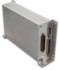
2.4.1 Cabling and Wiring Use AWG #24 or larger wire for all connections unless otherwise specified by the aircraft manufacturer or Garmin. The standard-density socket contacts supplied in the connector kit are compatible with up to AWG #20 wire (P431). In cases where some installations have more than one unit sharing a common circuit breaker, sizing and wire gauge is based on aircraft circuit breaker layout, length of wiring, current draw of units, and internal unit protection characteristics. Do not attempt to combine more than one unit on the same circuit breaker unless it is specified on aircraft manufacturer approved drawings. Ensure that routing of the wiring does not come in contact with sources of heat, RF or EMI interference. Check that there is ample space for the cabling and mating connectors. Avoid sharp bends in cabling and routing near aircraft control cables. 2.4.2 Cooling Requirements The GAD 43 has no cooling requirements. 2.4.3 Mounting Requirements NOTE Installation of the GAD 43 is restricted to locations in the aircraft that are consistent with the DO-160E categories defined in the GAD 43 Environmental Qualification Form (EQF), P/N 005-00496-07. General environmental specifications can be found in Section 1.4.3. The GAD 43 is designed to be mounted flat or on its side. If mounting the GAD 43 on its side, a minimum of four 6/32" screws must be used. If mounting the GAD 43 flat, a minimum of six 6/32" screws must be used. Figure 2-1. Side and Flat Mounting of GAD 43 Page 2-2 Rev. B GAD 43 Installation Manual 190-00899-00
-
 1
1 -
2
-
3
-
4
-
5
-
6
-
7
-
8
-
9
-
10
-
11
-
12
-
13
-
14
-
 15
15 -
 16
16 -
 17
17 -
 18
18 -
 19
19 -
 20
20 -
 21
21 -
 22
22 -
 23
23 -
 24
24 -
 25
25 -
26
-
27
-
28
-
29
-
30
-
31
-
32
-
33
-
34
-
35
-
36
-
37
-
38
-
39
-
40
-
41
-
42
-
43
-
44
-
45
-
46
-
47
-
48
-
49
-
50
-
51
-
52
-
53
-
54
-
55
-
56
-
57
-
58
-
59
-
60
-
61
-
62
 |
 |
