Garmin GAD 43e Installation Manual - Page 21
INSTALLATION PROCEDURE, 1 Unpacking Unit, 2 Special Tools Required, 3 Equipment Mounting, 4 Unit
 |
View all Garmin GAD 43e manuals
Add to My Manuals
Save this manual to your list of manuals |
Page 21 highlights
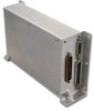
3. INSTALLATION PROCEDURE 3.1 Unpacking Unit Carefully unpack the equipment and make a visual inspection of the unit for evidence of damage incurred during shipment. If the unit is damaged, notify the carrier and file a claim. To justify a claim, save the original shipping container and all packing materials. Do not return the unit to Garmin until the carrier has authorized the claim. Retain the original shipping containers for return shipments. If the original containers are not available, a separate cardboard container should be prepared that is large enough to accommodate sufficient packing material to prevent movement. 3.2 Special Tools Required Crimp Tool A crimp tool meeting MIL specification M22520/2-01 and a positioner/locator are required to ensure consistent, reliable crimp contact connections for the rear D-sub connectors. Refer to Table 3-2 for a list of recommended crimp tools. 3.3 Equipment Mounting NOTE Installation of the GAD 43 is restricted to locations in the aircraft that are consistent with the DO-160E categories defined in the GAD 43 Environmental Qualification Form (EQF), P/N 005-00496-07. General environmental specifications can be found in Section 1.4.3. The GAD 43 should be mounted in a dry location, which may be pressurized or unpressurized. A location away from heating vents or other sources of heat generation is optimal. The unit should be mounted on a flat surface using the flanges provided on the GAD 43 unit. The mounting surface should provide sufficient electrical bond to the aircraft to minimize radiated electro-magnetic interference (EMI). Cabling must also be fabricated to fit each particular aircraft. 3.4 Unit Replacement Whenever the GAD 43 is removed and reinstalled, verify that the slide-lock is engaged on both sides of the connector. The GDU 620 provides a configuration interface for the GAD 43. If the unit was serviced or if a new unit is being installed, verify that the configuration is correct by comparing the previously completed checkout log to the configuration settings shown on the GDU 620. After configuration, power up the system including GDU 620 and GAD 43 and verify that no failure or error messages are displayed. NOTE The installation configuration settings are stored in the GDU 620 configuration module and will be retained when the GAD 43 is replaced with a new unit. If a new GAD 43 is reinstalled in place of an existing unit, it will be required to enter configuration mode on the GDU 620 to verify that the GAD 43 configuration is correct for the installation. 3.5 Cabling and Wiring The GAD 43 connector kit includes the connector and crimp contacts. Make the crimp connections with a crimp tool as specified in Table 3-2. Refer to the interconnection diagrams in APPENDIX C for the appropriate interconnections. Use 22 or 24 AWG wire for all connections except for power. Use 22 AWG for power/ground. Once the cable assemblies have been made, position the cable so that there is sufficient length to allow for the installation of the GAD. Route the wiring bundle as appropriate. Avoid sharp bends. GAD 43 Installation Manual 190-00899-00 Page 3-1 Rev. B
-
 1
1 -
2
-
3
-
4
-
5
-
6
-
7
-
8
-
9
-
10
-
11
-
12
-
13
-
14
-
15
-
 16
16 -
 17
17 -
 18
18 -
 19
19 -
 20
20 -
 21
21 -
 22
22 -
 23
23 -
 24
24 -
 25
25 -
 26
26 -
27
-
28
-
29
-
30
-
31
-
32
-
33
-
34
-
35
-
36
-
37
-
38
-
39
-
40
-
41
-
42
-
43
-
44
-
45
-
46
-
47
-
48
-
49
-
50
-
51
-
52
-
53
-
54
-
55
-
56
-
57
-
58
-
59
-
60
-
61
-
62
 |
 |
