Garmin GDL 69/69A Installation Manual - Page 19
Remote Mount Rack, GDL 69/69A Remote Mount Rack, G1000 Modular Rack, Remote Switches - specs
 |
View all Garmin GDL 69/69A manuals
Add to My Manuals
Save this manual to your list of manuals |
Page 19 highlights
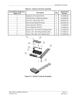
Installation Procedure 2.4.2 Remote Mount Rack The remote mount rack can be installed in a variety of locations, such as the electronics bay, behind the instrument panel, under the seat or behind the rear baggage area. Leave sufficient clearance between the GDL 69/69A and any obstruction. Install the rack in accordance with AC43.13-2A Chapter 2 Radio Installations. The remote mount rack should be mounted to a surface known to have sufficient structural integrity to withstand additional inertial forces imposed by a 1.86 pound unit (1.72 lbs. for GDL 69). If it is necessary to build a shelf or bracket to mount the GDL 69/69A rack or if is not certain that the chosen location is of sufficient structural integrity, refer to Appendix C. Refer to Figure 1-2 for the GDL 69/69A remote mount rack dimensions. The rack can be mounted vertically using four 8-32 pan head screws (MS35206, AN526 or equivalent.) It can also be mounted horizontally using four 6-32 100° counter-sunk flathead screws (MS24693, AN507R or equivalent.) Ensure that the rack has a ground path to the airframe by having at least one mounting screw in contact with the airframe to minimize radiated electromagnetic interference (EMI). BACK PLATE ASSEMBLY P/N: 011-00796-35 CONNECTOR KIT ASSEMBLY P/N: 011-00997-00 GDL 69 P/N: 011-00986-00 GDL 69A P/N: 001-00987-00 GDL 69 REMOTE MOUNT RACK P/N: 115-00658-00 Figure 2-2. GDL 69/69A Remote Mount Rack 2.4.3 G1000 Modular Rack The G1000 modular rack is used to install the GDL 69/69A in the standard G1000 integrated avionics system rack. This modular rack may be mounted behind the instrument panel or in the avionics bay. Refer to Figure 1-3 for the GDL 69/69A G1000 modular rack dimensions. This STC covers the installation of the GDL 69/69A modular rack into the installed G1000 integrated avionics system rack, but does not cover the installation of the G1000 integrated avionics system rack. 2.4.4 Remote Switches Installation of rocker switches should be made on a flat surface and located at a convenient location within the cabin. Each rocker switch installed must be properly marked of its function. Use of rocker switches vs. toggle switches will prevent the possibility of raising and lowering the volume at the same time or raising and lowering the channels at the same time. Wire used for discrete switches should be 24 AWG (MIL Spec M22759) and should be routed as appropriate, avoiding kinking or sharp bends. Figure 2-3 shows typical rocker switches. GDL 69/69A Installation Manual 190-00355-02 Page 2-3 Revision E
-
 1
1 -
2
-
3
-
4
-
5
-
6
-
7
-
8
-
9
-
10
-
11
-
12
-
13
-
 14
14 -
 15
15 -
 16
16 -
 17
17 -
 18
18 -
 19
19 -
 20
20 -
 21
21 -
 22
22 -
 23
23 -
 24
24 -
25
-
26
-
27
-
28
-
29
-
30
-
31
-
32
-
33
-
34
-
35
-
36
-
37
-
38
-
39
-
40
-
41
-
42
-
43
-
44
-
45
-
46
-
47
-
48
-
49
-
50
-
51
-
52
-
53
-
54
-
55
-
56
-
57
-
58
-
59
-
60
-
61
-
62
-
63
-
64
-
65
-
66
-
67
-
68
-
69
-
70
 |
 |
