Garmin GDL 69/69A Installation Manual - Page 22
Table 2-3., Recommended Crimp Tools, 24 AWG, Wire Gauge, Crimping Tool, Positioner, Insertion,
 |
View all Garmin GDL 69/69A manuals
Add to My Manuals
Save this manual to your list of manuals |
Page 22 highlights
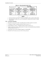
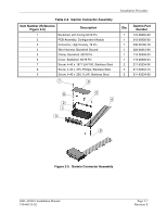
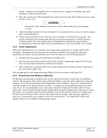
Installation Procedure Table 2-3. Recommended Crimp Tools Wire Gauge Military P/N Positronic ITT Cannon AMP Daniels Astro Hand Crimping Tool M22520/2-01 9507 995-0001-584 601966-1 AFM8 615717 20-24 AWG Positioner Insertion/ Extraction Tool M22520/2-09 M81969/1-04 9502-3 M81969/1-04 995-0001-739 n/a 601966-6 91067-1 K42 M81969/1-04 615725 M81969/1-04 NOTE 1. Insertion/extraction tools from ITT Cannon are all plastic; others are plastic with metal tip. 2. Non-Garmin part numbers shown are not maintained by Garmin and are subject to change without notice. 2.5.2 Connector Assembly 1. Backshell Cast Housing: Provides a mounting point for all other connector accessories. 2. Configuration Module: Installation details provided in Section 2.5.3. 3. D-Sub-Miniature Connector: Installation details provided in Section 2.5.3. 4. Spider Ground System: Allows shield grounds to be made to the backshell housing. Installation details provided in Section 2.5.5. 5. Strain Relief Tab: Provides strength and support to wiring bundles. 6. Backshell Lid: Provides easy access when servicing connector. Page 2-6 Revision E GDL 69/69A Installation Manual 190-00355-02
-
 1
1 -
2
-
3
-
4
-
5
-
6
-
7
-
8
-
9
-
10
-
11
-
12
-
13
-
14
-
15
-
16
-
 17
17 -
 18
18 -
 19
19 -
 20
20 -
 21
21 -
 22
22 -
 23
23 -
 24
24 -
 25
25 -
 26
26 -
 27
27 -
28
-
29
-
30
-
31
-
32
-
33
-
34
-
35
-
36
-
37
-
38
-
39
-
40
-
41
-
42
-
43
-
44
-
45
-
46
-
47
-
48
-
49
-
50
-
51
-
52
-
53
-
54
-
55
-
56
-
57
-
58
-
59
-
60
-
61
-
62
-
63
-
64
-
65
-
66
-
67
-
68
-
69
-
70
 |
 |
