Garmin GDL 69/69A Installation Manual - Page 21
Cabling and Wiring, CAUTION - gdl 69a antenna
 |
View all Garmin GDL 69/69A manuals
Add to My Manuals
Save this manual to your list of manuals |
Page 21 highlights
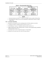
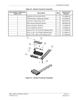
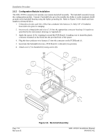
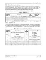
Installation Procedure 2.5 Cabling and Wiring Wiring should be installed in accordance with AC 43.13-1B Chapter 11. When wire separation cannot be achieved, the following issues should be addressed: • The cable harness should not be located near flight control cables and control, high electrical capacity lines or fuel lines • The cable harness should be located in a protected area of the aircraft • Do not route cable near high-energy sources Refer to the interconnection diagrams in Appendix D for the appropriate wiring. Once the cable assemblies have been made, attach the cable connector to the rear of the rack. Route the wiring bundle as appropriate. Use 22 or 24 AWG wire for all connections except for power. Use 22 AWG for power/ground. Avoid sharp bends. After the cable assemblies are made assemble the backshell as shown in Figure 2-6. Then install the backshell connector to the rear plate using the screws provided in the connector kit. After the rack is installed, assemble the rear plate into the rack. 2.5.1 Wiring Harness Allow adequate space for installation of cables and connectors. The installer supplies and fabricates all of the cables. Except for the antenna connection, all electrical connections are made through a 78-pin DSubminiature connector provided by Garmin. Construct the wiring harness according to the information contained in this and the following sections. Cable lengths will vary depending upon installation. Strip all wires going to the 78-pin D-Sub connector 1/8". Insert the wire into the pin and crimp with one of the recommended (or equivalent) crimping tools. Insert the pin into the 78-pin D-Sub connector housing location as specified by the interconnect drawing in Appendix D. Verify the pin is properly engaged into the connector by gently tugging on the wire. Route and secure the cable run from the GDL 69/69A to the other units away from sources of electrical noise. Section 3 defines the electrical characteristics of all input and output signals. Required connectors and associated hardware are supplied with the connector kit. See Appendix D for interconnect wiring diagrams. CAUTION Check wiring connections for errors before inserting the GDL 69/69A into the rack or mounting bracket. Incorrect wiring could cause component damage. Table 2-2. Pin Contact Part Numbers Wire Gauge Garmin P/N Military P/N AMP Positronic ITT Cannon 78 pin connectors (P691) 22-28 AWG 336-00021-00 M39029/58-360 204370-2 MC8522D 030-2042-000 GDL 69/69A Installation Manual 190-00355-02 Page 2-5 Revision E
-
 1
1 -
2
-
3
-
4
-
5
-
6
-
7
-
8
-
9
-
10
-
11
-
12
-
13
-
14
-
15
-
 16
16 -
 17
17 -
 18
18 -
 19
19 -
 20
20 -
 21
21 -
 22
22 -
 23
23 -
 24
24 -
 25
25 -
 26
26 -
27
-
28
-
29
-
30
-
31
-
32
-
33
-
34
-
35
-
36
-
37
-
38
-
39
-
40
-
41
-
42
-
43
-
44
-
45
-
46
-
47
-
48
-
49
-
50
-
51
-
52
-
53
-
54
-
55
-
56
-
57
-
58
-
59
-
60
-
61
-
62
-
63
-
64
-
65
-
66
-
67
-
68
-
69
-
70
 |
 |
