Garmin GDL 69/69A Installation Manual - Page 26
Spider and Connector Assembly Procedure, Spider Installation Drawing
 |
View all Garmin GDL 69/69A manuals
Add to My Manuals
Save this manual to your list of manuals |
Page 26 highlights
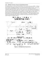
Installation Procedure 2.5.5 Spider and Connector Assembly Procedure 3x 11 10 1 2x 8 2 6 7 2x 5 4 24 AWG 24" 3 TO GROUND (AIRFRAME OR 9 TAB ON RACK) 16 AWG Figure 2-7. Spider Installation Drawing 1. At one end of the shielded cable (7), strip back 2.0" to 3.5" of jacket while retaining the shield. Trim away enough to leave 0.5" of shield exposed. 2. Strip 1/8" of insulation from one of the AWG #24 wires (4) on the Spider. 3. Connect the prepared AWG #24 Spider wire (4) to the shield (7) using an approved shield termination technique. Installation Options: a) Slide a solder sleeve (6) onto the prepared wire assembly (4, 7) and shrink with a heat gun. The size of solder sleeve must accommodate the number of conductors present in the cable. Reference the following MIL-Specs for solder sleeves (M83519/1-1, M83519/1-2, M83519/1-3, M83519/1-4, M83519/1-5). b) Solder the prepared wire assembly (4, 7). Slide a piece of shrink tube (6) onto the prepared wire assembly and shrink using a heat gun. The size of shrink tube must accommodate the number of conductors present in the cable. 4. Strip 1/8" of insulation from the shielded cable end and crimp a pin (8) to each of the conductors (7). 5. Insert crimped pins and wires (7, 8) into the appropriate housing location as specified by the installation wiring diagrams. 6. Repeat steps 1 through 3 as needed for the remaining shielded cables (7). Use only one Spider wire (4) per shield. Remaining AWG #24 wires should be tied back and dressed with shrink tubing. 7. Wrap the cable bundle with Silicone Fusion Tape (Garmin P/N: 249-00114-00 or a similar version) at the point where the backshell strain relief (10) and cast housing (1) contacts the cable Page 2-10 Revision E GDL 69/69A Installation Manual 190-00355-02
-
 1
1 -
2
-
3
-
4
-
5
-
6
-
7
-
8
-
9
-
10
-
11
-
12
-
13
-
14
-
15
-
16
-
17
-
18
-
19
-
20
-
 21
21 -
 22
22 -
 23
23 -
 24
24 -
 25
25 -
 26
26 -
 27
27 -
 28
28 -
 29
29 -
 30
30 -
 31
31 -
32
-
33
-
34
-
35
-
36
-
37
-
38
-
39
-
40
-
41
-
42
-
43
-
44
-
45
-
46
-
47
-
48
-
49
-
50
-
51
-
52
-
53
-
54
-
55
-
56
-
57
-
58
-
59
-
60
-
61
-
62
-
63
-
64
-
65
-
66
-
67
-
68
-
69
-
70
 |
 |
