Garmin STRIKER 5cv Owner s Manual PDF - Page 9
Marking Your Present Location as a, Waypoint - sonar
 |
View all Garmin STRIKER 5cv manuals
Add to My Manuals
Save this manual to your list of manuals |
Page 9 highlights
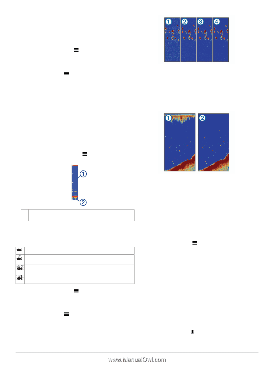
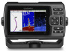
option provides a good balance between a quickly scrolling image and targets that are less distorted. Setting the Bottom Search Limit You can set a maximum depth at which the auto range feature searches for the bottom. A lower limit acquires data about the bottom faster than a higher limit. 1 From a sonar screen, select > Sonar Setup > Bottom Search Limit. 2 Select a range. Sonar Appearance Settings From a sonar view, select > Sonar Setup > Appearance. Color Scheme: Sets the color scheme. Edge: Highlights the strongest signal from the bottom to help define the hardness or softness of the signal. A-Scope: Displays a vertical flasher along the right side of the screen that shows instantaneously the range to targets along a scale. Fish Symbols: Sets how the sonar interprets suspended targets. Turning on the A-Scope The a-scope is a vertical flasher along the right side of the fullscreen sonar view. This feature expands the most recently received sonar data so that it is easier to see. It can also be helpful for detecting fish that are close to the bottom. NOTE: This feature is not available on all sonar screens. From the full screen page, select > Sonar Setup > Appearance > A-Scope. When you adjust the interference setting from off through À low , medium , and high , noise is gradually removed, Á Â Ã but there is little effect on the strong target returns. You should use the lowest interference setting that achieves the desired improvement to remove interference from the screen. Correcting installation issues that cause noise is the best way to eliminate interference. Surface Noise: Hides sonar returns near the surface of the water. Hiding surface noise helps reduce screen clutter. A-Scope À Diameter of the sonar cone at the present depth Á Configuring the Appearance of Suspended Targets NOTE: Configuring the appearance of suspended targets on one screen applies that setting to all screens. NOTE: This feature is not available on all sonar views. Shows suspended targets as symbols. Shows suspended targets as symbols with target depth information. Shows suspended targets as symbols with background sonar information. Shows suspended targets as symbols with background sonar information and target depth information. 1 From a sonar screen, select > Sonar Setup > Appearance > Fish Symbols. 2 Select an option. Sonar Noise Rejection Settings From a sonar view, select > Sonar Setup > Noise Reject. Interference: Adjusts the sensitivity to reduce the effects of interference from nearby sources of noise. Surface noise is caused by interference between the À transducer and water. You can hide surface noise to help Á reduce clutter. Wider beam widths (lower frequencies) can show more targets, but can generate more surface noise. TVG: Reduces surface noise. This control is best used for situations when you want to control and suppress clutter or noise near the water surface. It also allows for the display of targets near the surface that are otherwise hidden or masked by surface noise. Overlay Number Settings You can customize the data shown on the sonar screen. NOTE: Not all features are available on all devices. From a sonar screen, select > Overlay Numbers. Navigation Inset: Shows the navigation inset when the vessel is navigating to a destination. Device Voltage: Shows the voltage of the device. Speed: Shows the vessel's current speed. Time of Day: Shows the current time of day. Compass Tape: Shows the compass tape data bar. Depth: Shows the transducer's current depth. Water Temp.: Shows the current water temperature. Waypoints Waypoints are locations you record and store in the device. Marking Your Present Location as a Waypoint From any screen, select . Waypoints 5
-
 1
1 -
2
-
3
-
 4
4 -
 5
5 -
 6
6 -
 7
7 -
 8
8 -
 9
9 -
 10
10 -
 11
11 -
 12
12 -
 13
13 -
 14
14 -
15
-
16
 |
 |