GE CGP650SETSS Installation Instructions - Page 13
Cont. - appliance
 |
View all GE CGP650SETSS manuals
Add to My Manuals
Save this manual to your list of manuals |
Page 13 highlights
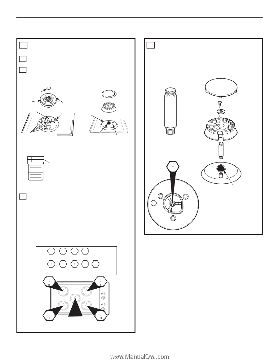
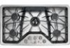
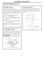
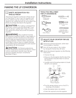
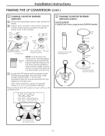
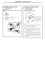
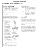
Installation Instructions MAKING THE LP CONVERSION (CONT.) 3 CHANGE COOKTOP BURNER ORIFICES A Remove the top grates, burner caps, and burner heads. B Using a 7mm nut driver, remove the top burner orifices. These may be accessed through the burner holes in the cooktop. Inner burner cap Burner base Electrode Outer burner cap Burner base OR Burner base Burner cap Burner head Orifice spuds located through these openings Tri-Ring Burner Orifice spud located Electrode through this opening NOTE: On all burners, the orifices have a spring-loaded Retainer retaining ring around the hex Ring head to hold the orifice in the nut driver during installation and removal. A slight amount of force is required to push the nut driver down over the ring. C Locate the LP/Propane orifices shipped inside the literature package. They will have a digit number and the letter "L" on the side. (Important: Save the orifices removed from the appliance for future use.) Each orifice will show a series of engraved marks, (I, II, III, IV or V), located on the top. These marks denote the location of each orifice to the cooktop burner. 3 CHANGE COOKTOP BURNER ORIFICES (CONT.) CENTER BURNER 17,000 BTU/hr Extra Large Burner (PGP976 Models) Extended spud for center extra large burner IV Burner Cap Set Screw Choke Burner Head Extended Spud Base Orifice spud located through this opening I x1 II x2 III x1 IV x1 For PGP976 Models I x1 II x2 III x1 V x1 V x3, Tall For PGP986 & CGP650 Models See instructions for center burner 13
-
 1
1 -
2
-
3
-
4
-
5
-
6
-
7
-
 8
8 -
 9
9 -
 10
10 -
 11
11 -
 12
12 -
 13
13 -
 14
14 -
 15
15 -
 16
16 -
 17
17 -
 18
18 -
19
-
20
-
21
-
22
-
23
-
24
-
25
-
26
-
27
-
28
-
29
-
30
-
31
-
32
 |
 |