GE CGP650SETSS Installation Instructions - Page 4
PREPARING THE OPENING, Installation Instructions
 |
View all GE CGP650SETSS manuals
Add to My Manuals
Save this manual to your list of manuals |
Page 4 highlights
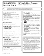
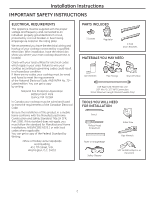
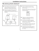
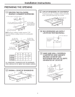
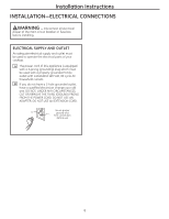
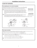
Installation Instructions PREPARING THE OPENING 1 MAINTAIN THE FOLLOWING MINIMUM CLEARANCE DIMENSIONS 13″ MAX. Depth of overhead cabinets 3 3/4 MIN. 30″ MIN. clearance from countertop to unprotected overhead surface 18″ MIN. height from countertop to nearest cabinet on either side of unit 3 CUTOUT DIMENSIONS OF COUNTERTOP To ensure accuracy, it is best to make a template when cutting the opening in the counter. 33-7/8" length of cut 19-1/8" width cut 16-15/16″ 2-1/2″ MIN. from cutout to front of countertop NOTE: All gas cooktop models require 7/16″ free area below cooktop bottom to combustible material. C - MIN. from cooktop to rear vertical combustibles A - MIN. from cooktop to right vertical combustibles 4 RECOMMENDED GAS SUPPLY LOCATION FROM BACKWALL 1" Min. From Backwall Recommended gas supply location 7″ From Cutout Center Line B - MIN. from cooktop to left vertical combustibles 36" or wider cabinet base A PGP976 5" PGP986 11" CPG650 11" B C 3" 1-5/16" 11" 2" 11" 2" ALL HORIZONTAL CLEARANCES MUST BE MAINTAINED FOR A MINIMUM OF 18" ABOVE THE COOKING SURFACE. 2 OVERALL COOKTOP DIMENSIONS 36″ 21″ Cooktop 3-1/4″ 18-7/8″ 33-11/16″ 5 MAKE SURE WALL COVERINGS, COUNTERTOP AND CABINETS AROUND COOKTOP CAN WITHSTAND HEAT (UP TO 200°F) GENERATED BY COOKTOP Wall covering, cabinets and countertop must withstand heat up to 200°F 4
-
 1
1 -
 2
2 -
 3
3 -
 4
4 -
 5
5 -
 6
6 -
 7
7 -
 8
8 -
 9
9 -
 10
10 -
11
-
12
-
13
-
14
-
15
-
16
-
17
-
18
-
19
-
20
-
21
-
22
-
23
-
24
-
25
-
26
-
27
-
28
-
29
-
30
-
31
-
32
 |
 |
