GE CGP650SETSS Installation Instructions - Page 14
Change Cooktop Burner, Orifices Cont. - griddle
 |
View all GE CGP650SETSS manuals
Add to My Manuals
Save this manual to your list of manuals |
Page 14 highlights
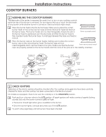
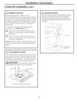
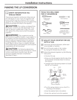
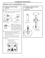
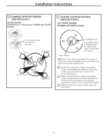
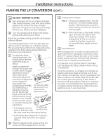
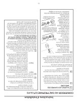
Installation Instructions 3 CHANGE COOKTOP BURNER ORIFICES (CONT.) CENTER BURNER 20,000 BTU/hr Tri-Ring Burner (PGP986 and CGP650 Models) 3 CHANGE COOKTOP BURNER ORIFICES (CONT.) LEFT FRONT BURNER (PGP986 and CGP650 Models) Orifice spuds located through these openings. Main Orifice Tall V Main Orifice V Tall V Simmer Orifice V Tall Main Orifice Griddle Screw The griddle screw is marked with N for natural gas and L for liquefied petroleum. Main Orifice NOTE: The main orifice is located in the center of the burner, while the griddle screw is located to the right of the center of the burner. D Install the LP Propane orifices and griddle screw (on PGP986 and CGP650 models only) in their precise locations as noted in the earlier illustrations. E Return the natural gas orifices and griddle screw to the bracket and attach the bracket and the instruction sheet to the pressure regulator using the screw removed previously. F Replace the burner bases, heads, caps and top grates. 14
-
 1
1 -
2
-
3
-
4
-
5
-
6
-
7
-
8
-
 9
9 -
 10
10 -
 11
11 -
 12
12 -
 13
13 -
 14
14 -
 15
15 -
 16
16 -
 17
17 -
 18
18 -
 19
19 -
20
-
21
-
22
-
23
-
24
-
25
-
26
-
27
-
28
-
29
-
30
-
31
-
32
 |
 |
