GE DCVH485EKMS Use and Care Manual - Page 12
Installation Instructions, LOCATION OF YOUR DRYER
 |
UPC - 084691191261
View all GE DCVH485EKMS manuals
Add to My Manuals
Save this manual to your list of manuals |
Page 12 highlights
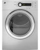
Installation Instructions UNPACKING YOUR DRYER Tilt the dryer sideways and remove the foam shipping pads by pulling at the sides and breaking them away from the dryer legs. Be sure to remove all of the foam pieces around the legs. Remove the bag containing the literature. LOCATION OF YOUR DRYER MINIMUM CLEARANCE OTHER THAN ALCOVE OR CLOSET INSTALLATION Minimum clearance to combustible surfaces and for air openings are: • 0 inch clearance both sides • 3 inches front and rear Consideration must be given to provide adequate clearance for proper operation and service. DRYER DIMENSIONS 23.5″ (598 mm) Front View 33.4″ (848 mm) ELECTRICAL CONNECTION Electrical Connection Back View 27.65″ (702 mm) 10.0″ (254 mm) 4.0″ 20.75″ (527 mm) (101 mm) 12 42.9″ (1090 mm) Side View 33.4″ (848 mm) 25.7″ (653 mm)
-
 1
1 -
2
-
3
-
4
-
5
-
6
-
 7
7 -
 8
8 -
 9
9 -
 10
10 -
 11
11 -
 12
12 -
 13
13 -
 14
14 -
 15
15 -
 16
16 -
 17
17 -
18
-
19
-
20
-
21
-
22
-
23
-
24
-
25
-
26
-
27
-
28
-
29
-
30
-
31
-
32
-
33
-
34
-
35
-
36
-
37
-
38
-
39
-
40
-
41
-
42
-
43
-
44
-
45
-
46
-
47
-
48
-
49
-
50
-
51
-
52
-
53
-
54
-
55
-
56
-
57
-
58
-
59
-
60
-
61
-
62
-
63
-
64
-
65
-
66
-
67
-
68
-
69
-
70
-
71
-
72
-
73
-
74
-
75
-
76
-
77
-
78
-
79
-
80
-
81
-
82
-
83
-
84
-
85
-
86
-
87
-
88
-
89
-
90
-
91
-
92
-
93
-
94
-
95
-
96
-
97
-
98
-
99
-
100
-
101
-
102
-
103
-
104
-
105
-
106
-
107
-
108
 |
 |
