GE DPGT650EHWW Owners Manual - Page 22
Installation Instructions, CONNECTING AN ELECTRIC DRYER cont., WARNING
 |
UPC - 084691170303
View all GE DPGT650EHWW manuals
Add to My Manuals
Save this manual to your list of manuals |
Page 22 highlights
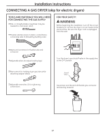
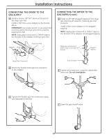
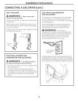
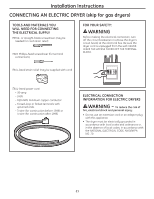
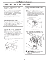
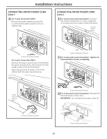
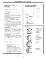
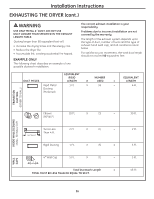
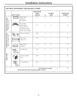
Installation Instructions CONNECTING AN ELECTRIC DRYER (cont.) ELECTRICAL REQUIREMENTS FOR ELECTRIC DRYERS This dryer must be connected to an individual branch circuit, protected by the required time-delay fuses or circuit breakers. A three- or four-wire, single phase, 120/240V or 120/208V, 60Hz, 30-amp circuit is required. If the electric supply does not meet the above specifications, then call a licensed electrician. CONNECTING DRYER POWER CORD (cont .) B For 3-wire and 4-wire Connection: Install a UL-listed strain relief into the power cord entry hole beneath the terminal block. Thread a UL-listed 30A, 240V, 3-wire or 4-wire, #10 AWG minimum copper conductor power cord through the strain relief. GROUNDING INSTRUCTIONS This dryer must be connected to a grounded metal, permanent wiring system, or an equipmentgrounding conductor must be run with the circuit conductors and connected to the equipment grounding terminal on the appliance. Strain Relief CONNECTING DRYER POWER CORD NOTE: Since January 1, 1996, the National Electrical Code requires that new constructions utilize a 4-wire connection to an electric dryer. A 4-wire cord must also be used where local codes do not permit grounding through the neutral. 3-wire connection is NOT for use on new construction. A Remove the terminal block access cover located at the upper back. (3-wire Connection Shown) C For 3-wire and 4-wire Connection: Connect the two hot lines to the outer screws of the terminal block. Connect outer screws (3-wire Connection Shown) WARNING: Do not make a sharp bend or crimp wiring/conductor at connections. 22
-
 1
1 -
2
-
3
-
4
-
5
-
6
-
7
-
8
-
9
-
10
-
11
-
12
-
13
-
14
-
15
-
16
-
 17
17 -
 18
18 -
 19
19 -
 20
20 -
 21
21 -
 22
22 -
 23
23 -
 24
24 -
 25
25 -
 26
26 -
 27
27 -
28
-
29
-
30
-
31
-
32
-
33
-
34
-
35
-
36
-
37
-
38
-
39
-
40
-
41
-
42
-
43
-
44
-
45
-
46
-
47
-
48
-
49
-
50
-
51
-
52
-
53
-
54
-
55
-
56
-
57
-
58
-
59
-
60
-
61
-
62
-
63
-
64
-
65
-
66
-
67
-
68
-
69
-
70
-
71
-
72
 |
 |
