GE GDT530PSDSS Installation Instructions - Page 11
Step 16, Connect Drain Line Cont., Step 17: Connect Power Supply
 |
View all GE GDT530PSDSS manuals
Add to My Manuals
Save this manual to your list of manuals |
Page 11 highlights
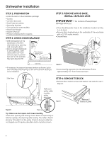
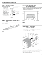
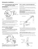
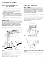
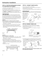
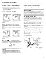
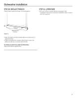
Dishwasher Installation STEP 16: CONNECT DRAIN LINE (Cont.) • Connect drain line to air gap, waste tee or disposer using the previously determined method. Secure hose with a screw-type clamp. Method 1 - Air gap with waste tee or disposer STEP 17: CONNECT POWER SUPPLY If a power cord with plug is already installed proceed to Step 18. WARNING: If house wiring is not 2-wire with ground, a ground must be provided by the installer. When house wiring is aluminum, be sure to use UL-Listed anti-oxidant compound and aluminum-to-copper connectors. Waste Tee Installation Disposer Installation Figure Y 756Dia60 756Dia61 Method 2 - "High drain loop" with waste tee or disposer With this method you will need the drain hose hanger set aside in Step 1. Fasten drain hose to underside of countertop with the provided hanger. Drain Hose Hanger 32" 18" Min. Min. 32" 18" Min. Min. Waste Tee Installation Disposer Installation Figure Z 05D-1294C IMP0O5DR-T1A29N4BT - When connecting drain line to disposer, check to be sure that drain plug has been removed. DISHWASHER WILL NOT DRAIN IF PLUG IS LEFT IN PLACE. Remove Drain Plug Tip: Avoid unnecessary service call charges for a no drain complaint . 1871 Art1 Make sure excess drain hose has been pulled through the cabinet opening. This will prevent excess hose in the dishwasher cavity from becoming kinked or crushed by the dishwasher. ADVERTENCIA: Si el cableado doméstico no cuenta con un cable de 2 hilos con conexión a tierra, un instalador debe realizar una conexión a tierra. Cuando el cableado doméstico es de aluminio, asegúrese de usar un compuesto antioxidante y conectores de aluminio a cobre aprobados por UL. In this step you will need the junction box cover and the #10 Hex head screw from the screws set aside in Step 1. • Secure house wiring to the back of the junction box with a strain relief. • Locate the 3 dishwasher wires, (white, black and green) with the stripped ends coming out of the AC jumper. Use UL listed wire nuts of appropriate size to connect incoming ground to green, white to white and black to black. • Install the junction box cover using #10 hex head screw. Check to be sure that wires are not pinched under the cover. • Make sure that the junction box cover is resting on the mounting bracket. NOTE: Do not remove the Junction Box Bracket. White Ground (Green) AC Jumper Ground Screw Figure AA Black Junction Box Bracket 11
-
 1
1 -
2
-
3
-
4
-
5
-
 6
6 -
 7
7 -
 8
8 -
 9
9 -
 10
10 -
 11
11 -
 12
12 -
 13
13 -
 14
14 -
 15
15 -
 16
16 -
17
-
18
-
19
-
20
-
21
-
22
-
23
-
24
-
25
-
26
-
27
-
28
-
29
-
30
-
31
-
32
 |
 |
