GE GFDR485EFRR Installation Instructions - Page 27
Side Venting
 |
View all GE GFDR485EFRR manuals
Add to My Manuals
Save this manual to your list of manuals |
Page 27 highlights
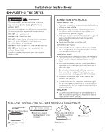
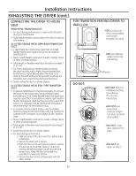
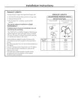
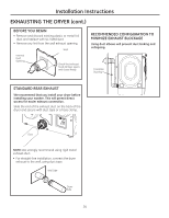
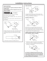
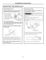
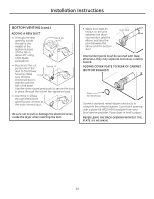
Installation Instructions SIDE VENTING: Dryer Exhaust to right of cabinet for Electric models only. Dryer Exhaust to left of cabinet for Gas and Electric models. WARNING - Fire Hazard Disconnect dryer from electrical supply. Wear gloves and arm guards. Close the back opening with cover plate (Kit WE1M454). Failure to do so may result in electrical shock or lacerations. TAB LOCATION Bend tab up 45° Not for gas Through the rear opening, locate the tab in the middle of the appliance base. Lift the tab to about 45°, using a flat-blade screwdriver. ADDING A NEW DUCT Fixing hole Portion "A" Remove Right screw and save Left Remove desired knockout (one only) Detach and remove the right or left side knockout as desired. Remove the screw inside the dryer exhaust duct and save. Pull the duct out of the dryer. Fixing hole Left side exhaust Reconnect the cut portion (A) of the duct to the blower housing. Make sure that the shortened duct is aligned with the tab in the base. Use the screw saved previously to secure the duct in place through the tab on the appliance base. ADDING ELBOW AND DUCT FOR EXHAUST TO LEFT OR RIGHT SIDE OF CABINET Internal duct A 15 3ø4" Cut the duct as shown and keep portion A. Rear opening • Insert the 4" elbow through the rear opening and connect the elbow to the dryer internal duct. • Insert the 4" duct through the side opening and connect it to the elbow. Side opening Do not pull or damage the electrical wires and do not remove the vinyl cover from the electrical components inside the dryer when inserting the duct. A slight interference may occur between the exhaust and the wire components. 27
-
 1
1 -
2
-
3
-
4
-
5
-
6
-
7
-
8
-
9
-
10
-
11
-
12
-
13
-
14
-
15
-
16
-
17
-
18
-
19
-
20
-
21
-
 22
22 -
 23
23 -
 24
24 -
 25
25 -
 26
26 -
 27
27 -
 28
28 -
 29
29 -
 30
30 -
 31
31 -
 32
32 -
33
-
34
-
35
-
36
-
37
-
38
-
39
-
40
-
41
-
42
-
43
-
44
-
45
-
46
-
47
-
48
-
49
-
50
-
51
-
52
-
53
-
54
-
55
-
56
-
57
-
58
-
59
-
60
-
61
-
62
-
63
-
64
-
65
-
66
-
67
-
68
-
69
-
70
-
71
-
72
-
73
-
74
-
75
-
76
-
77
-
78
-
79
-
80
-
81
-
82
-
83
-
84
-
85
-
86
-
87
-
88
-
89
-
90
-
91
-
92
-
93
-
94
-
95
-
96
-
97
-
98
-
99
-
100
-
101
-
102
-
103
-
104
-
105
-
106
-
107
-
108
-
109
-
110
-
111
-
112
-
113
-
114
-
115
-
116
-
117
-
118
-
119
-
120
-
121
-
122
-
123
-
124
-
125
-
126
-
127
-
128
-
129
-
130
-
131
-
132
-
133
-
134
-
135
-
136
-
137
-
138
-
139
-
140
-
141
-
142
-
143
-
144
 |
 |