GE GFDR485EFRR Installation Instructions - Page 29
Bottom Venting Cont.
 |
View all GE GFDR485EFRR manuals
Add to My Manuals
Save this manual to your list of manuals |
Page 29 highlights
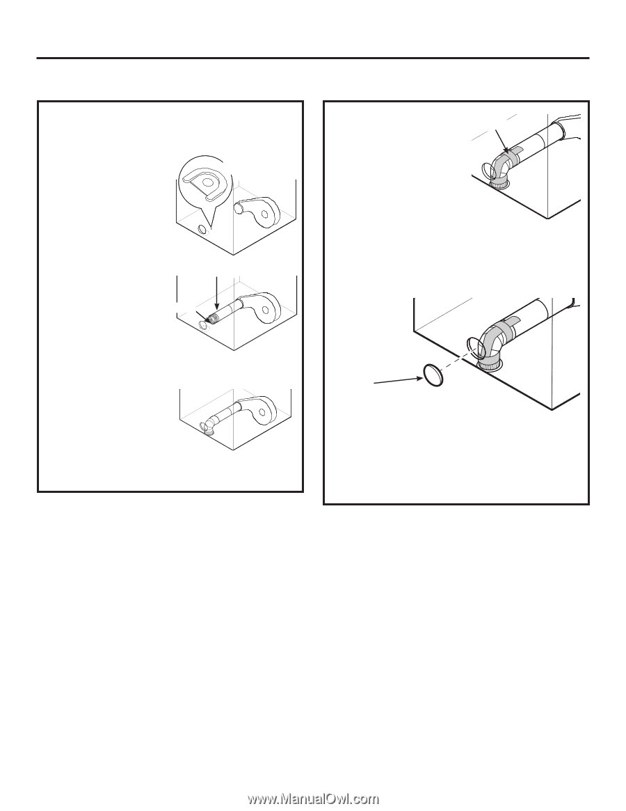
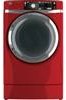
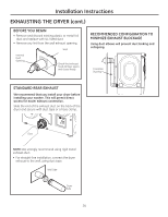
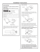
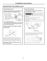
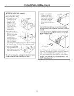
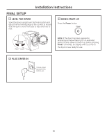
Installation Instructions BOTTOM VENTING (cont.) ADDING A NEW DUCT • Through the rear opening, locate the tab in the middle of the appliance base. Lift the tab to about 45° using a flat-blade screwdriver. Bend tab up 45° • Reconnect the cut portion (A) of the Portion "A" duct to the blower housing. Make sure that the Fixing hole shortened duct is aligned with the tab in the base. Use the screw saved previously to secure the duct in place through the tab on the appliance base. • Insert the 4" elbow through the bottom opening and connect to the dryer internal duct. Be sure not to pull or damage the electrical wires inside the dryer when inserting the duct. • Apply duct tape as shown on the joint between the dryer internal duct and the elbow, and also the joint between the elbow and the bottom duct. Duct tape Internal duct joints must be secured with tape; otherwise, they may separate and cause a safety hazard. ADDING COVER PLATE TO REAR OF CABINET (BOTTOM EXHAUST) Plate (Kit WE1M454) Connect standard metal elbows and ducts to complete the exhaust system. Cover back opening with a plate (Kit WE1M454) available from your local service provider. Place dryer in final location. NEVER LEAVE THE BACK OPENING WITHOUT THE PLATE. (Kit WE1M454.) 29
-
 1
1 -
2
-
3
-
4
-
5
-
6
-
7
-
8
-
9
-
10
-
11
-
12
-
13
-
14
-
15
-
16
-
17
-
18
-
19
-
20
-
21
-
22
-
23
-
 24
24 -
 25
25 -
 26
26 -
 27
27 -
 28
28 -
 29
29 -
 30
30 -
 31
31 -
 32
32 -
 33
33 -
 34
34 -
35
-
36
-
37
-
38
-
39
-
40
-
41
-
42
-
43
-
44
-
45
-
46
-
47
-
48
-
49
-
50
-
51
-
52
-
53
-
54
-
55
-
56
-
57
-
58
-
59
-
60
-
61
-
62
-
63
-
64
-
65
-
66
-
67
-
68
-
69
-
70
-
71
-
72
-
73
-
74
-
75
-
76
-
77
-
78
-
79
-
80
-
81
-
82
-
83
-
84
-
85
-
86
-
87
-
88
-
89
-
90
-
91
-
92
-
93
-
94
-
95
-
96
-
97
-
98
-
99
-
100
-
101
-
102
-
103
-
104
-
105
-
106
-
107
-
108
-
109
-
110
-
111
-
112
-
113
-
114
-
115
-
116
-
117
-
118
-
119
-
120
-
121
-
122
-
123
-
124
-
125
-
126
-
127
-
128
-
129
-
130
-
131
-
132
-
133
-
134
-
135
-
136
-
137
-
138
-
139
-
140
-
141
-
142
-
143
-
144
 |
 |