GE GG40T06PVK Use and Care Manual - Page 20
Installation Checklist
 |
View all GE GG40T06PVK manuals
Add to My Manuals
Save this manual to your list of manuals |
Page 20 highlights
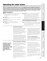
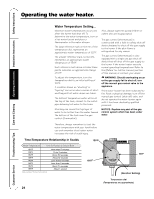
Operating Instructions Installation Instructions Safety Instructions Installation Checklist A. Water Heater Location ❑ Close to area of vent. ❑ Indoors and protected from freezing temperatures. ❑ Proper clearance from combustible surfaces observed and water heater not installed on carpeted floor. ❑ Sufficient fresh air supply for proper operation of water heater. ❑ Air supply free of corrosive elements and flammable vapors. B. Water Supply ❑ Water heater completely filled with water. ❑ Air purged from water heater and piping. ❑ Water connections tight and free of leaks. ❑ Provisions made to protect area from water damage. ❑ Sufficient room to service heater. ❑ Combustible materials, such as clothing, cleaning materials, rags, etc. clear of the base of the heater. ❑ Clearances of 1" from combustion air inlet openings observed ❑ Flammable vapor sensor is not blocked. Care and Cleaning Troubleshooting Tips C. Gas Supply ❑ Gas line equipped with shut-off valve, union and sediment trap. ❑ Approved pipe joint compound used. D. Relief Valve ❑ Temperature and Pressure Relief Valve properly installed and discharge line run to open drain. ❑ Discharge line protected from freezing. ❑ Soap and water solution used to check all connections and fittings for possible gas leak. ❑ Gas Company inspected installation (if required). E. Venting ❑ Flue baffle properly hung in top of heater's flue. ❑ Blower assembly properly installed. ❑ Vent connector(s) pitched upward to chimney (¼" per foot of length minimum) . ❑ Vent connector(s) securely fastened together with screws. ❑ Single wall vent connector(s) at least 6" from combustible material. ❑ Vapors from PVC cement and primer have dissipated prior to applying electrical power. 20 Customer Service
-
 1
1 -
2
-
3
-
4
-
5
-
6
-
7
-
8
-
9
-
10
-
11
-
12
-
13
-
14
-
 15
15 -
 16
16 -
 17
17 -
 18
18 -
 19
19 -
 20
20 -
 21
21 -
 22
22 -
 23
23 -
 24
24 -
 25
25 -
26
-
27
-
28
-
29
-
30
-
31
-
32
-
33
-
34
-
35
-
36
 |
 |