GE GG40T06PVK Use and Care Manual - Page 30
Gas Valve LED Error Codes
 |
View all GE GG40T06PVK manuals
Add to My Manuals
Save this manual to your list of manuals |
Page 30 highlights
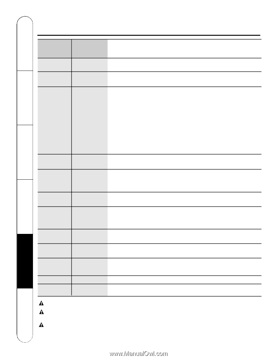
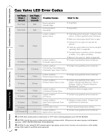
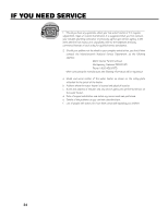
Operating Instructions Installation Instructions Safety Instructions Gas Valve LED Error Codes Care and Cleaning 1st Flash, Pause 1 second Slow Flash Fast Flash 1 Flash 2 Flashes 2 Flashes 2nd Flash, Pause 3 seconds N/A N/A 1 Flash 1 Flash 3 Flashes Possible Causes What To Do Normal operation. Standby Mode. Normal operation. Heat Mode. ● No problem. ● No problem. Lockout condition. Ignition Failure. Lockout condition. Flammable Vapors Present. ● Third failed ignition attempt. Unplug to reset control. Contact qualified service technician. ● Make sure manual gas shutoff valve is open. ● If pressure is too high, the valve will not operate. l● Clean any scale buildup from burner and pilot assembly. (Refer to page 26) ● The spark ignitor assembly could be damaged or broken. If so, replace assembly. ● Bleed air from gas line. (Refer to page 28) ● Contact local qualified service technician. Lockout condition. ● Contact local qualified service technician. FVD Interface Failure/Miswiring (Flammable Vapor Sensor Failure). 3 Flashes 3 Flashes 4 Flashes 4 Flashes 4 Flashes 5 Flashes LED Steady ON 1 Flash 3 Flash 1 Flash 2 Flash 3 Flash N/A Lockout condition. Pressure Switch Fails to Open. Lockout condition. Pressure Switch Fails to Close. Lockout condition. Line/Neutral Polarity Failure. Lockout condition. ECO Failure. Lockout condition. False Flame (Unwanted Flame Present). Vacation Mode Active Lockout condition. System Error, Cycle Power. ● Contact local qualified service technician. ● Contact local qualified service agent. Inspect vent pipe and dilution air inlet for blockage. (Refer to "Routine Preventive Maintenance" Section.) ● Check the electrical supply outlet. ● Contact local qualified service technician. ● Unplug to restart control. Contact local qualified service technician. ● Select desired temperature setting. ● Contact local qualified service technician. CAUTION: Make certain power to water heater is "OFF" before removing protective cover FOR ANY REASON. CAUTION: Label all wires prior to disconnection when servicing controls. Wiring errors can cause improper and dangerous operation. VERIFY PROPER OPERATION AFTER SERVICING. CAUTION: For your safety DO NOT attempt repair of gas piping, remote control, burners, vent connectors or other safety devices. Refer repairs to qualified service personnel. 30 Troubleshooting Tips Customer Service
-
 1
1 -
2
-
3
-
4
-
5
-
6
-
7
-
8
-
9
-
10
-
11
-
12
-
13
-
14
-
15
-
16
-
17
-
18
-
19
-
20
-
21
-
22
-
23
-
24
-
 25
25 -
 26
26 -
 27
27 -
 28
28 -
 29
29 -
 30
30 -
 31
31 -
 32
32 -
 33
33 -
 34
34 -
 35
35 -
36
 |
 |