GE GG40T06PVK Use and Care Manual - Page 31
Replacement Parts.
 |
View all GE GG40T06PVK manuals
Add to My Manuals
Save this manual to your list of manuals |
Page 31 highlights
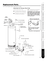
Safety Instructions Installation Instructions Operating Instructions Replacement Parts. For 40 and 50 gallon models using natural or LP gas. Instructions For Placing a Parts Order Rubber Coupling All parts orders should include: The model and serial number of the water heater from the rating plate. Specify type of gas (natural or LP) as marked on the rating plate. Part description (as noted below) and number of parts desired. CAUTION: For your safety, DO NOT attempt repair of gas piping, gas control (thermostat), burners, vent connectors or other safety devices. Refer repairs to qualified service personnel. Blower Assembly ** Heat Trap Nipple *Burner Assembly Kit ** Heat Trap Nipple Anode rod Flue baffle and hanger Dip tube Dip tube gasket Temperature and pressure relief valve The kit provides extra speed clips and tamper resistant screws. ** May differ in actual appearance. Drain valve Gas Control (Thermostat) Care and Cleaning Troubleshooting Tips Customer Service *Burner Flammable Vapor Sensor *Burner Access Door Gasket *Burner orifice *Spark Igniter Assembly *Burner Access Door *Pilot supply tube *Burner supply tube *Spark Igniter Wire *Sight Glass Jacket Door *Burner Access Door Grommet 31
-
 1
1 -
2
-
3
-
4
-
5
-
6
-
7
-
8
-
9
-
10
-
11
-
12
-
13
-
14
-
15
-
16
-
17
-
18
-
19
-
20
-
21
-
22
-
23
-
24
-
25
-
 26
26 -
 27
27 -
 28
28 -
 29
29 -
 30
30 -
 31
31 -
 32
32 -
 33
33 -
 34
34 -
 35
35 -
 36
36
 |
 |
