GE JGRS06BEJBB Installation Instructions - Page 4
Installation Instructions, INSTALL THE OVEN
 |
UPC - 084691098799
View all GE JGRS06BEJBB manuals
Add to My Manuals
Save this manual to your list of manuals |
Page 4 highlights
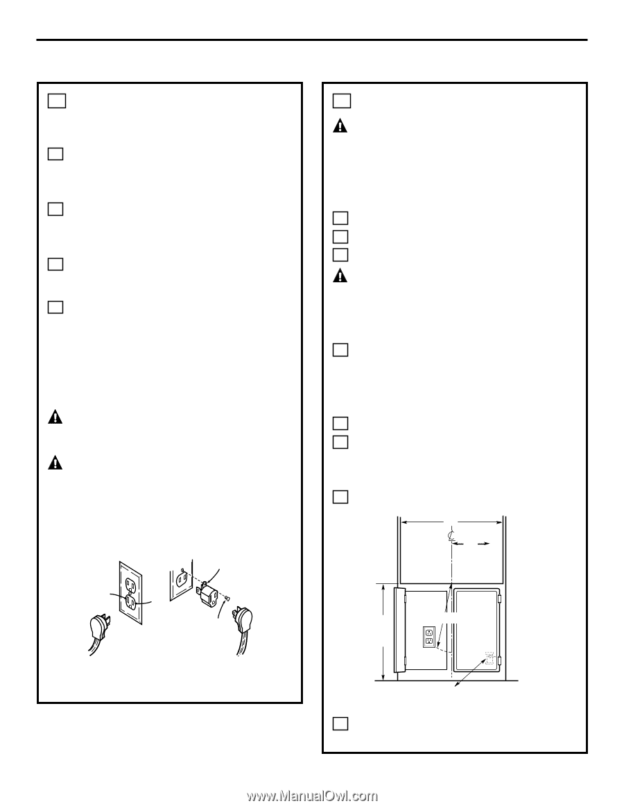
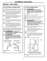
Installation Instructions INSTALL THE OVEN 4 ELECTRICAL CONNECTIONS An adequate electrical supply and outlet must be used to operate the electrical parts of your oven. A The oven cord has a three-prong plug and must be used with a properly grounded three-hole outlet with a standard 120 Volt, 60 cycle AC household current. B Install the electrical outlet below the oven on the left side, in a location that is easily reached through the cabinet doors. (See Fig. 6). C If you do not have a three-hole grounded outlet, have a qualified electrician change your old one. D A grounding adaptor will be needed to convert the old one until the outlet can be replaced. This method is only temporary, and a qualified electrician should test it to be sure it meets requirements. Always unplug the oven cord before making any electrical repairs to the oven. When unplugging the oven, always grasp the plug, never the cord. WARNING: NEVER USE AN EXTENSION CORD TO CONNECT THE OVEN TO THE ELECTRICAL SUPPLY. WARNING: Do not under any circumstances cut or remove grounding prong from oven cord. Failure to provide proper polarization may create a hazardous condition. Plug with ground prong properly polarized and grounded receptacle Polarized receptacle properly grounded Metal Eyelet Ground N L Receptacle Plate Mounting Screw Preferred Method Fig. 4 Temporary Method Fig. 5 5 GAS CONNECTIONS WARNING: Do not operate the burners of this oven when using L.P. (bottled) gas before converting the pressure regulator and burner orifice for L.P. gas usage. See page 2 for all gas requirements. A Shut off the gas supply at the shut-off valve. B Remove the existing oven (if necessary). C Discard any old or used connectors. WARNING: Never reuse old flexible connectors. The use of old flexible connectors can cause gas leaks and personal injury. Always use new connectors when installing a gas appliance. D Be sure no strain has been placed on the connecting line assembly. To prevent any leaks, use a pipe joint compound that resists the action of L.P. gas on the male outside threads. E Use a 1/2″ gas inlet pipe. F The hole for the inlet pipe should be 8 1/2″ min. to 9 5/8″ max. right of the centerline and 23″ behind the front surface of the cabinet. G Install a shut-off valve to the pipe. 22″ 8 1/2″ MIN. 9 5/8″ MAX. Fig. 6 22″ 13 1/2″ TO 28″ Recommended Main Shut-OFF Location (The regulator also has a shut-off lever) H Remove the storage drawer and the oven door. 4
-
 1
1 -
 2
2 -
 3
3 -
 4
4 -
 5
5 -
 6
6 -
 7
7 -
 8
8 -
 9
9 -
 10
10 -
11
-
12
-
13
-
14
-
15
-
16
 |
 |