GE JGRS06BEJBB Installation Instructions - Page 5
Warning, Caution - installation instructions
 |
UPC - 084691098799
View all GE JGRS06BEJBB manuals
Add to My Manuals
Save this manual to your list of manuals |
Page 5 highlights
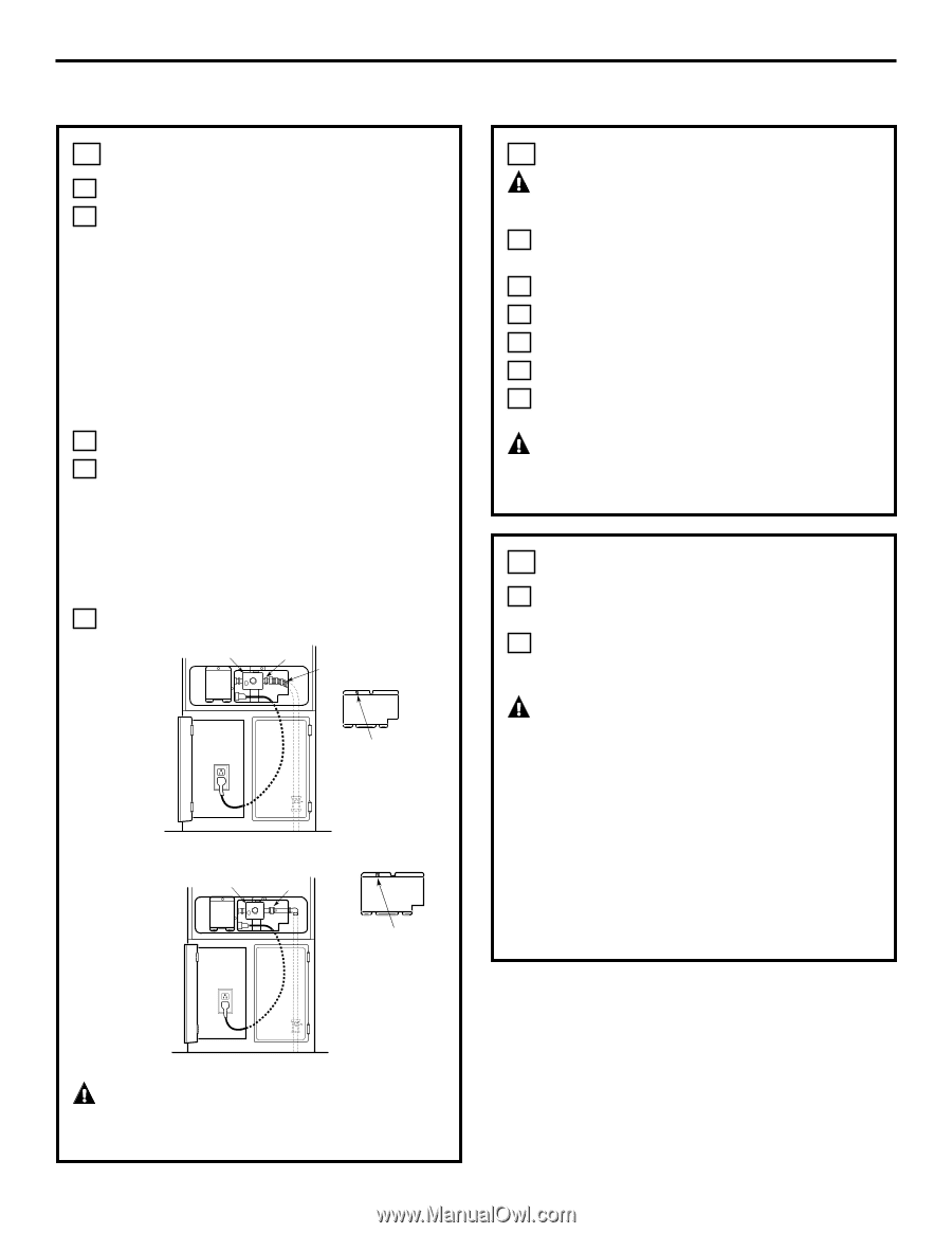
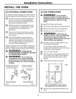
Installation Instructions 5 GAS CONNECTIONS (cont.) I Place the oven in the cutout. J Level the oven: 1. Place a spirit level on one of the oven racks. 2. If the oven is not level, adjust the leg levelers. With the oven in place, remove the regulator cover by carefully grasping the left side and pull until the spring clip is released. The pressure regulator inlet is accessible through the opening in the main back. K Remove regulator cover. L Through this opening connect: 1. The flexible connection and the adaptor (see Fig. 7). or 2. The rigid pipe connection and union to the shutoff valve (see Fig. 8). M Tighten the fitting. Pressure Regulator Adaptor Flexible Fig. 7 Connection Regulator Cover FLEXIBLE HOOK-UP Pressure Regulator Adaptor Fig. 8 Regulator Cover 6 CHECK FOR LEAKS WARNING: DO NOT USE OPEN FLAME TO CHECK FOR LEAKS! A Apply a soap solution to all connections: supply line, manifold and oven. B Turn on the main gas supply. C Check for any bubbles to form. D Turn off main gas supply. E Stop any leaks found. F Turn main gas supply on to make sure all leaks were stopped. WARNING: ALL LEAKS MUST BE STOPPED BEFORE ATTEMPTING TO LIGHT BURNERS. 7 PRESSURE TEST INFORMATION A The maximum allowable pressure for the regulator is 14″ W.C. B The minimum pressure needed to check the regulator setting is 11″ W.C. for L.P. gas and 5″ W.C. for Natural. CAUTION: The range and its individual shutoff valve must be disconnected from the gas supply piping system during any pressure testing of the gas supply system at test pressures in excess of 1/2 psig (pound per square inch gauge). The range must be isolated from the gas supply piping system by closing its individual manual shut-off valve during any pressure testing of the gas supply system at test pressures equal to or less than 1/2 psig. RIGID HOOK-UP WARNING: DO NOT FORCE! FORCING COULD DAMAGE THE FITTING, TUBING OR CAUSE LEAKING. 5
-
 1
1 -
 2
2 -
 3
3 -
 4
4 -
 5
5 -
 6
6 -
 7
7 -
 8
8 -
 9
9 -
 10
10 -
 11
11 -
12
-
13
-
14
-
15
-
16
 |
 |